A square loop of side 'a' with a capacitor of capacitance C is located between two current carrying long parallel wires as shown. The value of I in the wires in given as I=(I0)sinωt.
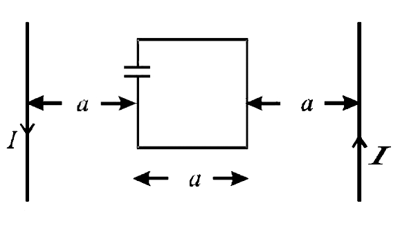
(a) Calculate maximum current in the square loop.
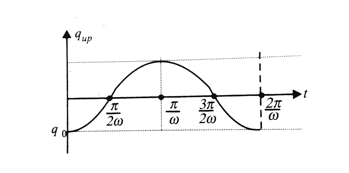
(b) Draw a graph between charges on the upper plates of the capacitor vs time.
Let us first find the flux through the loop due to left wire.
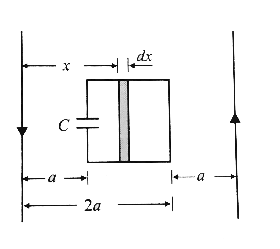
ϕL=∫2aaμ0I2π(loge2)
This flux will be in outward direction because magnetic field due to wire is in outward direction because anticlockwise direction is positive. Now flux due to right wire also be same because loop is placed symmtrically w.r.t. both wires. So net flux through the loop is
ϕ=2ϕL=μ0Iaπloge2 ltbr> Induced emf in the loop:
e=−dϕdt=−μ0a(loge2)π(dIdt)
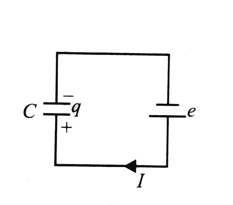
=−μ0I0ωaπ(loge2)cosωt ltbr> Negative sign indicates that induced emf will be in clockwise sence because anticlockwise sence is positive. Finally, induced emf in the loop is e=μ0ωaI0(loge2)πcosωt as shown in Fig. 3.93.
let q be the charge on the capacitor at any time, then
q=Ce=μ0I0ωaCloge2cosωtπ
Current I in the circuit: I=dqdt=μ0I0ω2aCloge2πsinωt
Hence, maximum current in the loop is ltbr> Imax=μ0I0ω2aCloge2π
Charge on the upper plate: qup=−q=−q0cosωt
where q0=μ0I0ωaC(loge2)π
The variation of qup with time as shown in Fig. 3.94.
Topper's Solved these Questions
- ELECTROMAGNETIC INDUCTIONBook:CENGAGE PHYSICS ENGLISHChapter:ELECTROMAGNETIC INDUCTIONExercise:Exercise 3.1
Explore 15 Videos
- ELECTROMAGNETIC INDUCTIONBook:CENGAGE PHYSICS ENGLISHChapter:ELECTROMAGNETIC INDUCTIONExercise:Exercise 3.2
Explore 27 Videos
- ELECTROMAGNETIC INDUCTIONBook:CENGAGE PHYSICS ENGLISHChapter:ELECTROMAGNETIC INDUCTIONExercise:compression type
Explore 7 Videos
- ELECTRICAL MEASURING INSTRUMENTSBook:CENGAGE PHYSICS ENGLISHChapter:ELECTRICAL MEASURING INSTRUMENTSExercise:M.C.Q
Explore 2 Videos
- ELECTRON,PHONTS,PHOTOELECTRIC EFFECT & X-RAYSBook:CENGAGE PHYSICS ENGLISHChapter:ELECTRON,PHONTS,PHOTOELECTRIC EFFECT & X-RAYSExercise:dpp 3.3
Explore 15 Videos
Similar Questions
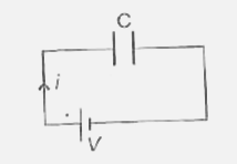
At a particle state the current in the circuit given below is i. The displacement current between the plates of the capacitor shown below is
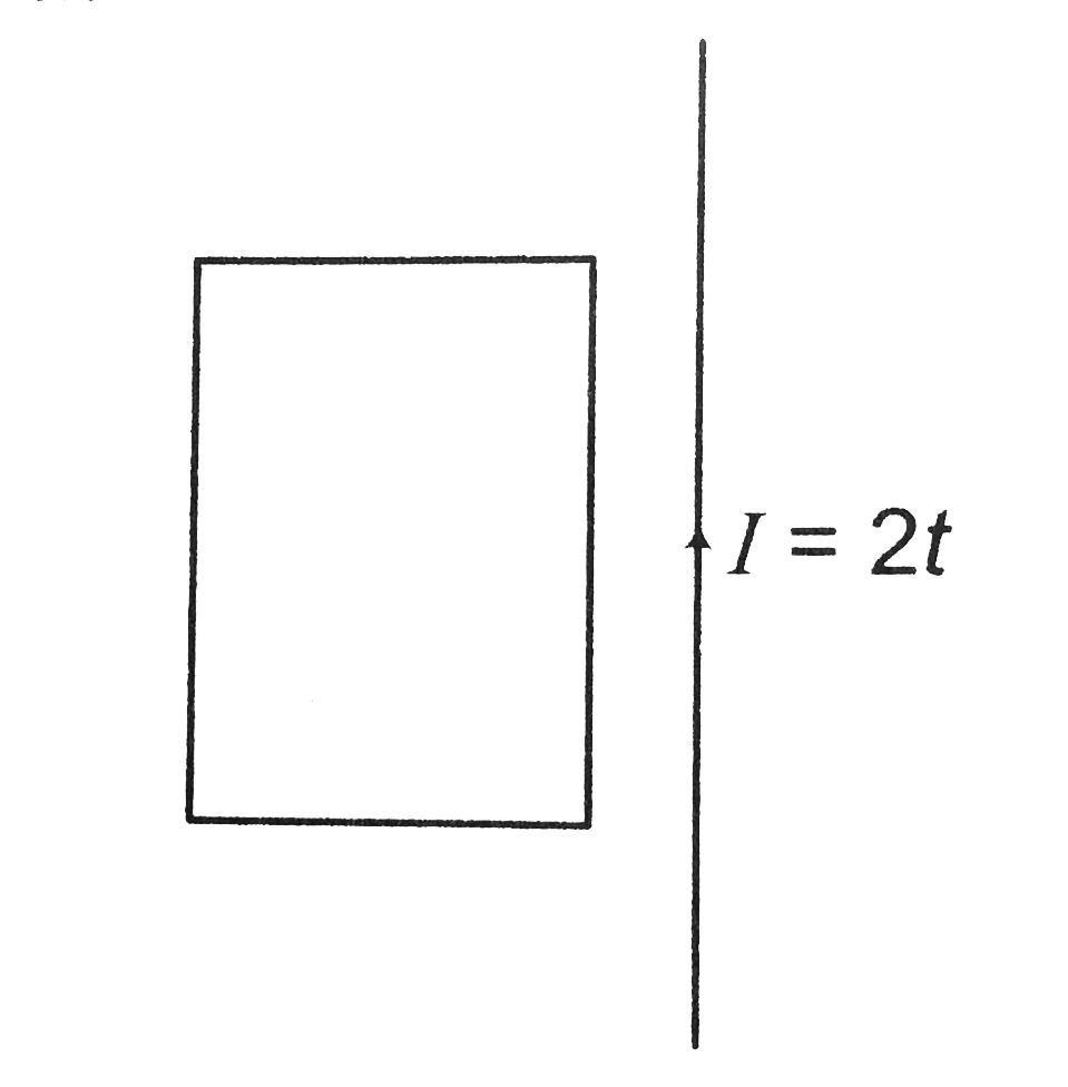
View SolutionA rectangular loop is placed to the left of large current carrying straight wire as shown in Figure. Current varies with time as I=2t. Find direction of induced current Iin in the square loop.
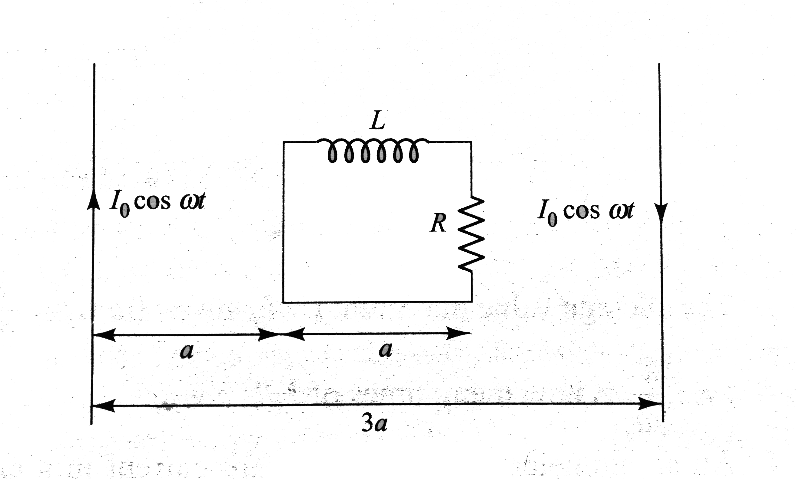
View SolutionIn fig, a square loop consistaing of an inductor of inductance L and resistor of resistance R is placed between two long parallel wires. The two long straight wires have time - varing current of magnitude I=(I0)cosωt but the direction of current in them are opposite.
The instantaneous current in the circuit will be
View SolutionIn fig, a square loop consistaing of an inductor of inductance L and resistor of resistance R is placed between two long parallel wires. The two long straight wires have time - varing current of magnitude I=(I0)cosωt but the direction of current in them are opposite
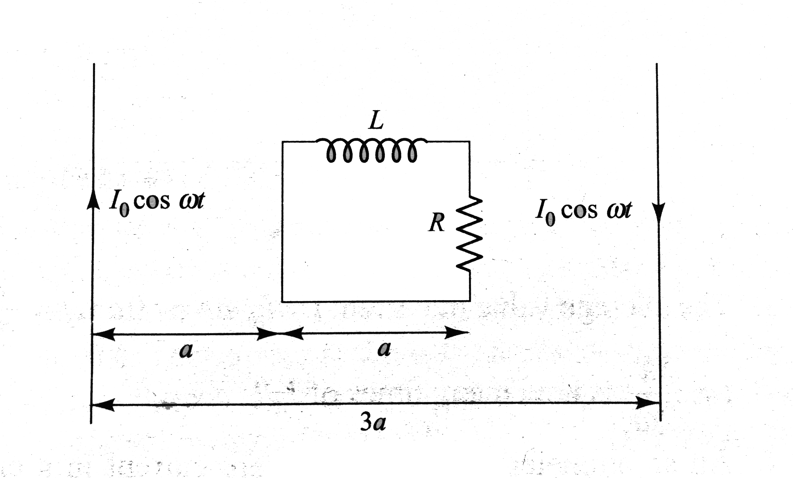
Total magnetic flux in this loop is
View SolutionIn fig, a square loop consistaing of an inductor of inductance L and resistor of resistance R is placed between two long parallel wires. The two long straight wires have time - varing current of magnitude I=(I0)cosωt but the direction of current in them are opposite
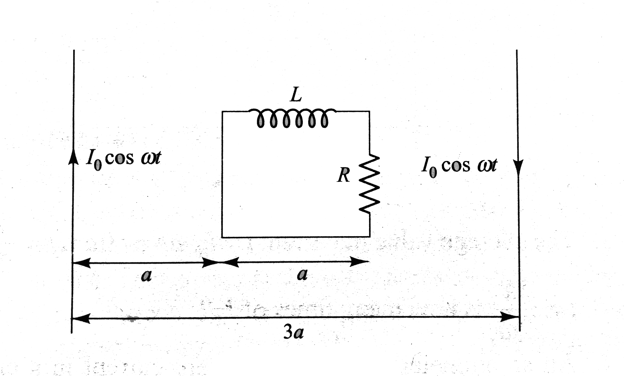
Magnitude of emf in this circuit only due to flux change associated with two long straight current carrying wires will be
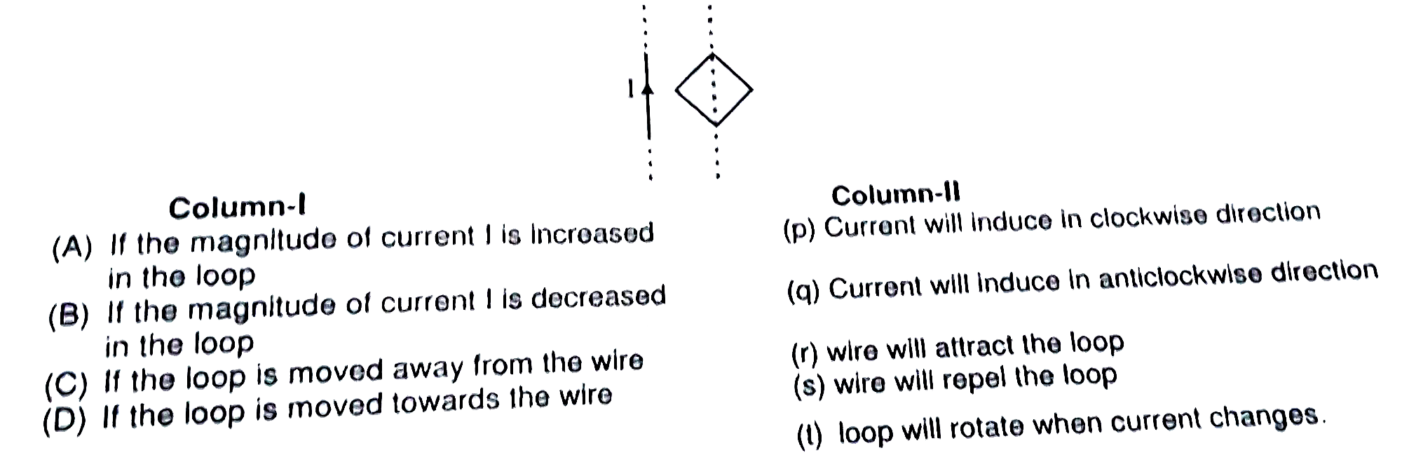
View SolutionA square loop of conducting wire is placed symmetrically near a long straight current carrying wire as shown. Match the statement in column-I with the corresponding results in column-II
View SolutionAn ac source of emf V=V0sinωt is connected to a capacitor of capacitance C. Deduce the expression for the current (I) flowing in it. Plot the graph of (i) Vvs.ωt,and (ii) Ivs.ωt
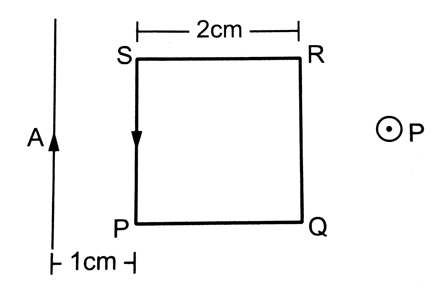
View SolutionA square loop PQRS carrying a current of 6.0 A is placed near a long wire carrying 10 A as shown in figure . (a) Show that the magnetic force acting on the part PQ is equal and opposite to that on the part RS. (b) Find the magnetic force on the square loop.
View SolutionA rigid square loop of side 'a' and carrying current I2 is lying on a horizontal surface near a long current I1 carrying wire in the same plane as shown in figure. The net force on the loop to the wire will be :
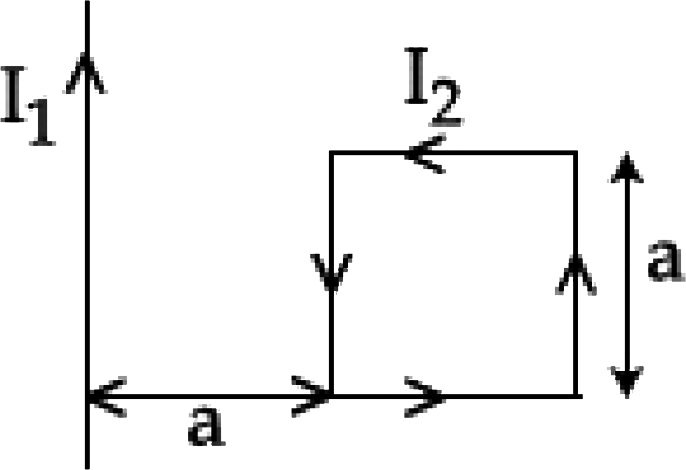
View SolutionA square loop of side a is placed at a distance a length away from a long wire carrying a current I1 . If the loop carries a current I2 as shown in the figure . Then the nature of the nature of the force and its amount is
View Solution
