At time t = 0 , terminal A in the circuit shown in the figure is connected to B by a key and alternating current I(t) = Iocos(ωt), with Io = 1 A and ω = 500 rads−1 starts flowing in it with the initial direction shown in the figure . At t = 7π/6ω , the keys is switched from B to D . Now onwards only A and D are connected . A total charge Q flows from the battery to charge the capacitor fully. If C = 20 μ , R = 10 Ω and the battery is deal with emf of 50 V , identify the correct statement(s).
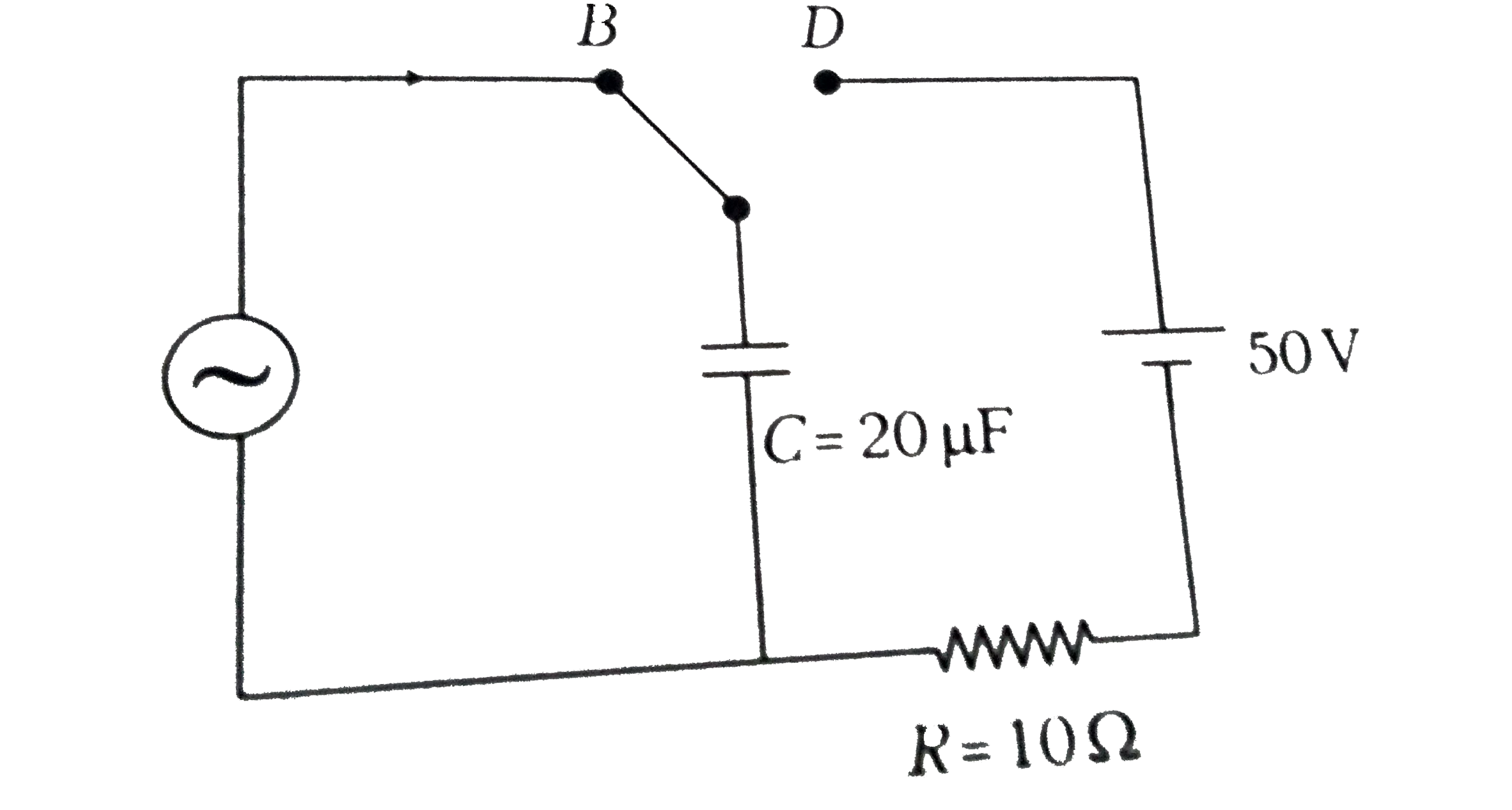
Magnitude of the maximum charge on the capacitor before t=7π6ωis1×10−3C
The current in the left part of the circuit just before t=7π6ω is clockwise.
Immidiately after A is connected to D, the current in R is 10 A.
Q=2×10⁻³C
The correct Answer is:C, D
If q represents the charge on capacitor's upper plate:
I(t)=(I0)cos(ωt)=dqdt⇒q(t)=I0ωsin(ωt)
Max charge =1A500rads−1=2×10⁻³C
Charge on upper plate at t=7π6ω=I0ωsin(7π6ω)=−I02ω
When capacitor is fully charged, charge on upper plate =50V
×20(μ)F=1×10⁻³C
∴Q=1×10⁻²C−(−I02ω)=2×10⁻³C
Voltage across capacitor when A and D are connected
=1×10⁻³C20×10−6μF=50V
Total voltage resistor =100V
⇒Current =100V10Ω 10 A
Current is anticlockwise.
Topper's Solved these Questions
- ALTERNATING CURRENTBOOK - CENGAGE PHYSICS ENGLISHCHAPTER - ALTERNATING CURRENTEXERCISE - Archives Integer
1 Videos
- ALTERNATING CURRENTBOOK - CENGAGE PHYSICS ENGLISHCHAPTER - ALTERNATING CURRENTEXERCISE - Single Correct Asnwer Type
27 Videos
- ALTERNATING CURRENTBOOK - CENGAGE PHYSICS ENGLISHCHAPTER - ALTERNATING CURRENTEXERCISE - Archives Single Correct
2 Videos
- ATOMIC PHYSICSBOOK - CENGAGE PHYSICS ENGLISHCHAPTER - ATOMIC PHYSICSEXERCISE - ddp.4.3
15 Videos
Similar Questions
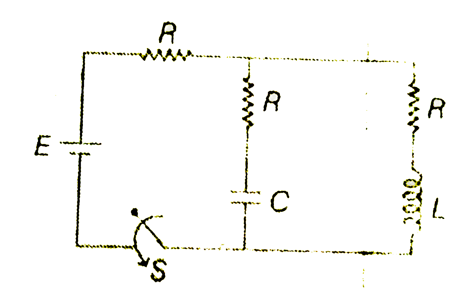
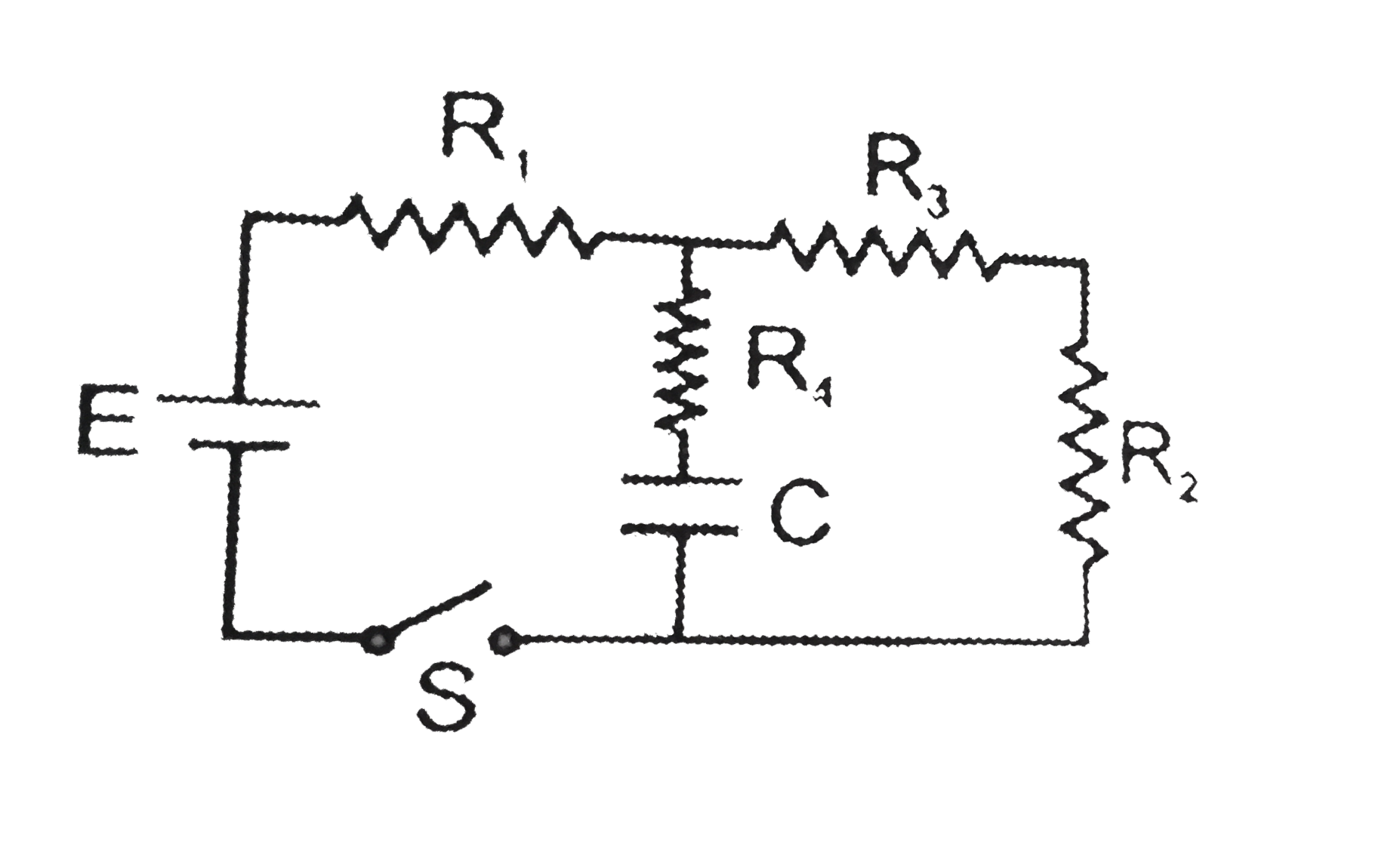
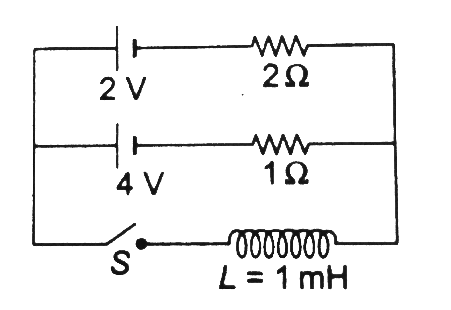
In the circuit as shown in the figure, switch S is added at t=0. Then:
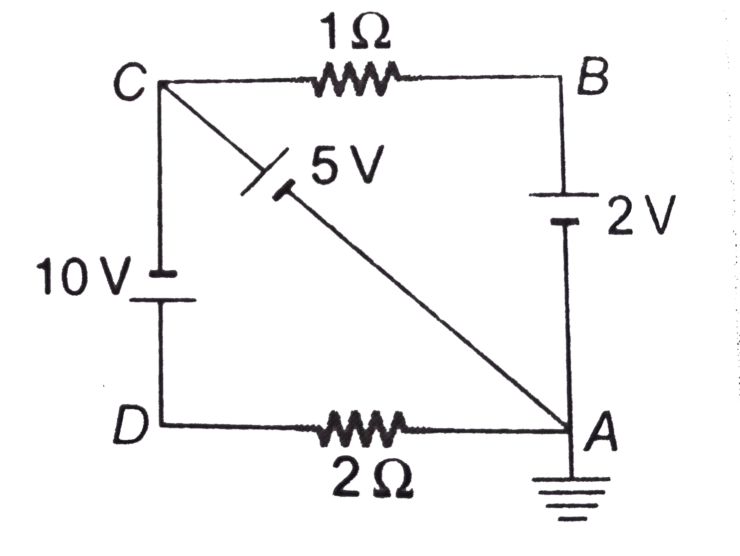
View SolutionIn the circuit shown in figure find the potentials of A,B,C and D and the current through 1Ω and 2Ω resistance.
View SolutionCurrent and voltage in AC are I = Io sin (ωt + π/4) and V = Vo sin (ωt - π/4), Then
View SolutionIn the circuit shown below, the key is pressed at time t = 0. The correct statement is
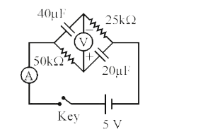
View SolutionIn the circuit shown in figure the switch S is closed at t = 0. A long time after closing the switch
View SolutionTwo coils have a mutual inductance 0.005 H. The alternating current changes in the first coil according to equation I = Iosinωt, where Io = 10 A and ω = 100π rads−1. The maximum value of emf in the second coil
is (in volt)
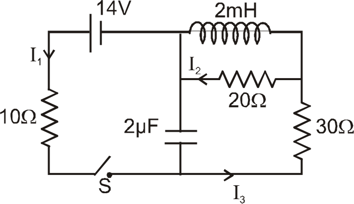
View SolutionIn the circuit shown, the switch is closed at t=0, the currents I1,I2 and I3 are
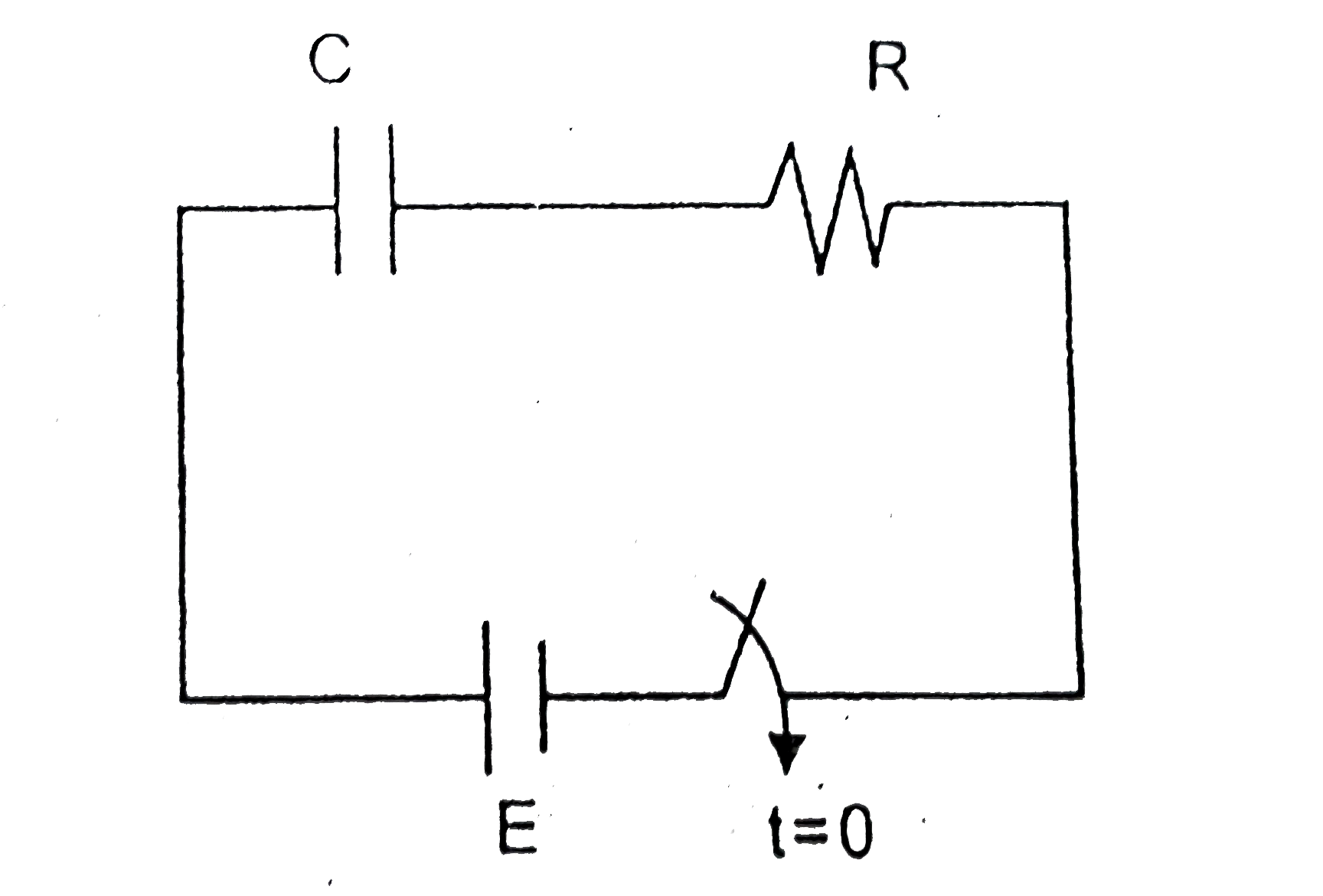
View SolutionIn the circuit shown key is closed at t=0 with capacitor initially uncharged.
View SolutionIn the circuit shown in figure switch S is closed at time t=0
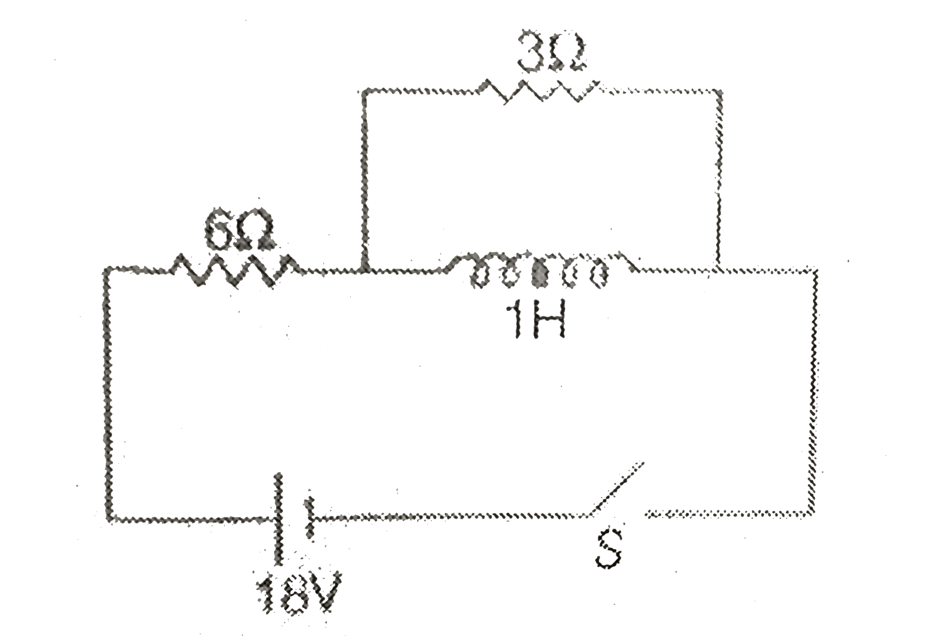
Current I from the battery at time t is given by
View SolutionIn the circuit shown, switch S is closed at time t=0. Find the current through the inductor as a function of time t.
View Solution
