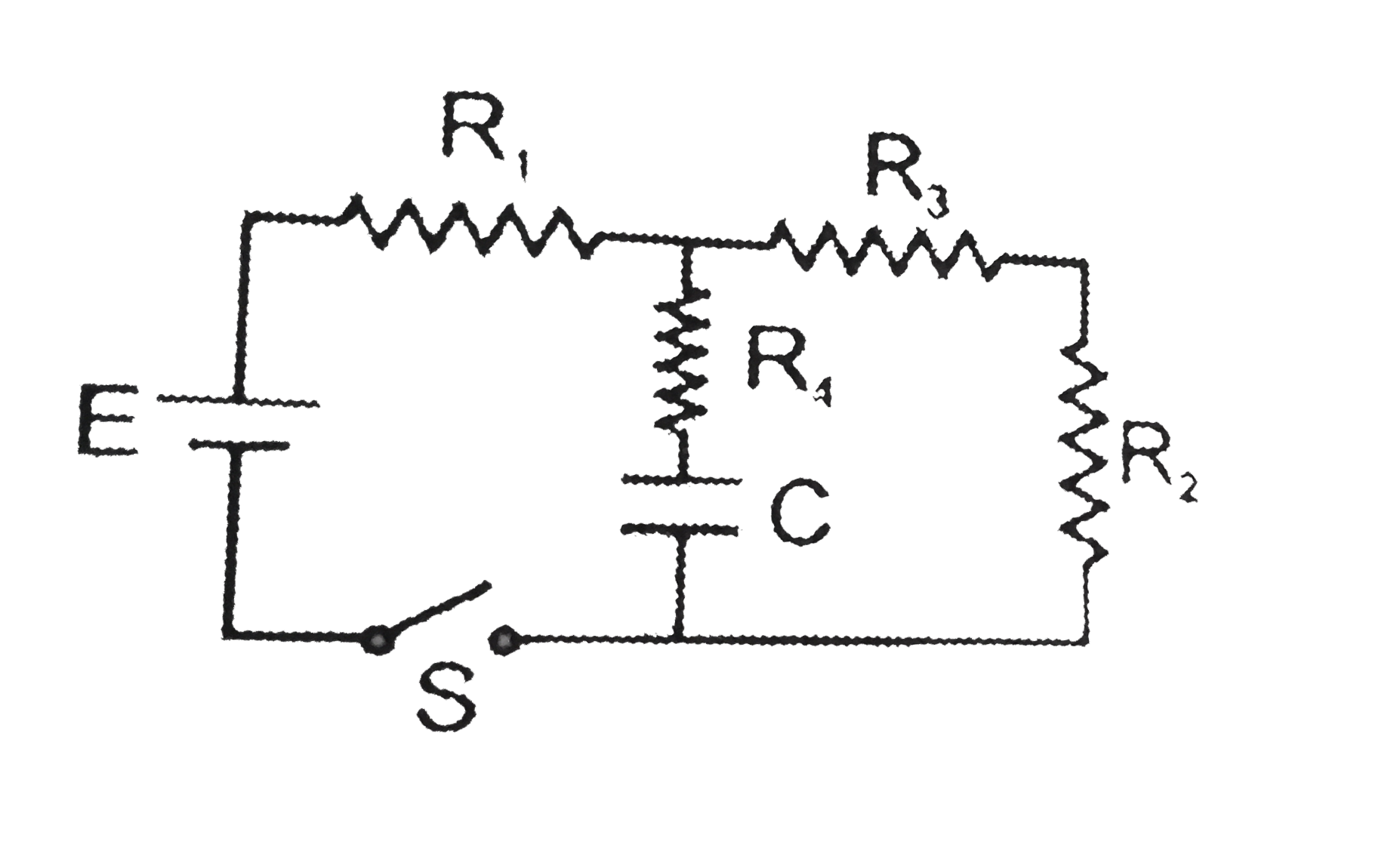
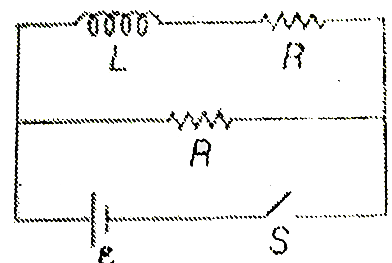
In the circuit as shown in the figure, switch S is added at t=0. Then:
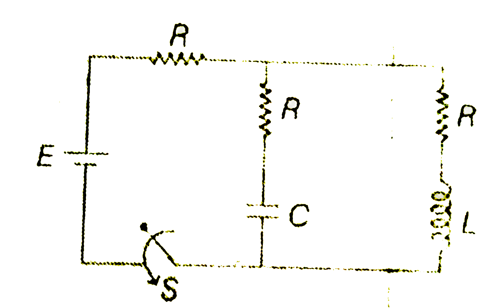
after a long time interval potential differences across capacitor and inductor will be equal
after a long time interval charge on a capacitor will be EC
after a long time interval curent in the inductory will be E/R
after a long time interval current through battery willl be same as the curren through it initially
The correct Answer is:D
Step by step video & image solution for In the circuit as shown in the figure, switch S is added at t=0. Then: by Physics experts to help you in doubts & scoring excellent marks in Class 12 exams.
Updated on:21/07/2023Similar Questions
In the circuit shown in the figure, switch S is closed at time t=0. Select the correct statements.
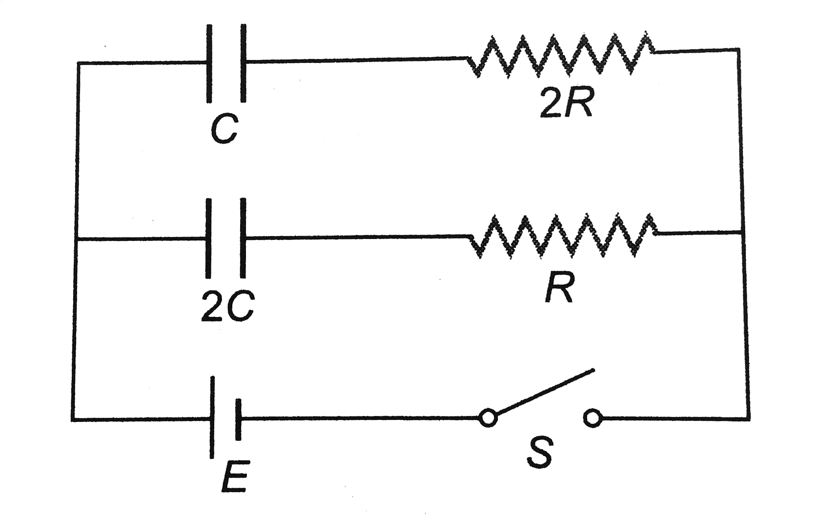
View SolutionIn the circuit shown in the figure, switch S is closed at time t=0. Select the correct statements.

View SolutionIn the circuit shown in figure switch S is closed at time t=0. The charge which passes through the battery in one time constant is
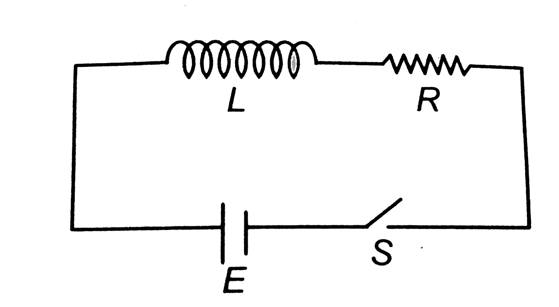
View SolutionIn the circuit shown in figure switch S is closed at time t=0
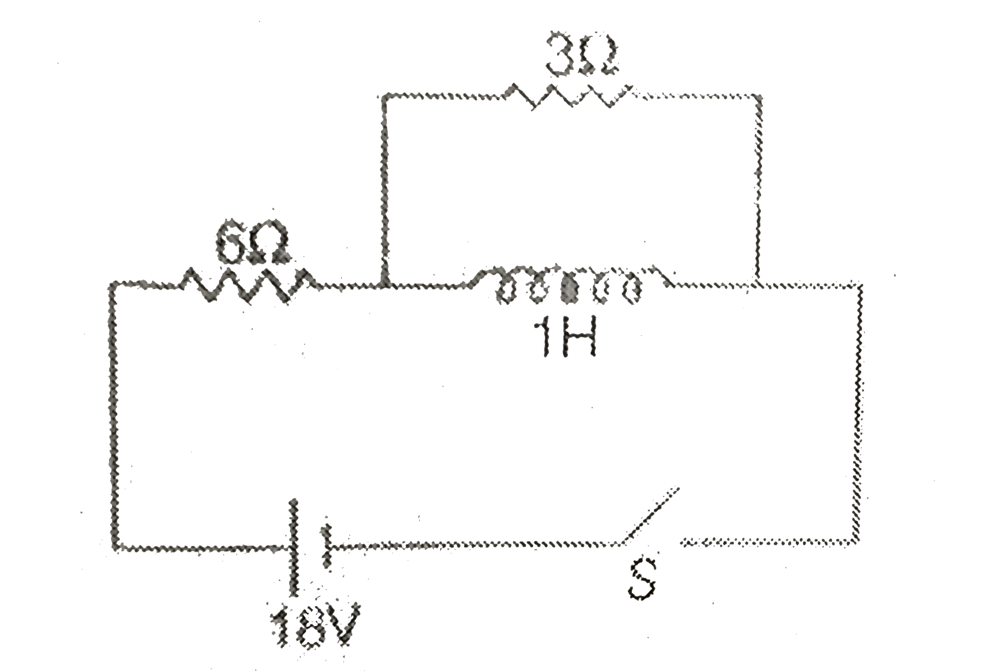
Current I from the battery at time t is given by
View SolutionIn the circuit shown in figure switch S is closed at time t=0
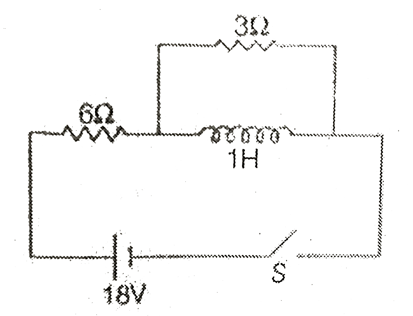
Takin left to right current through the indcutor as apositive current, current through inductor varies with time as
View SolutionIn the circuit shown in figure switch S is closed at time t=0
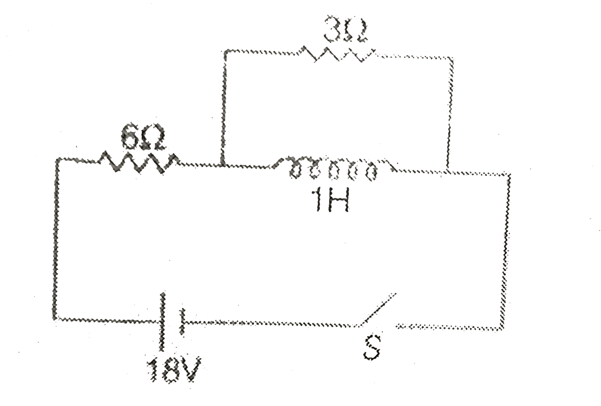
Potential difference across 3Ω resistance at time t is given by
View SolutionIn the circuit shown in figure, the switch S is closed at t=0. If VL is the voltge induced across the inductor and i is the instantaneous current, the correct variation of VL versus is given by
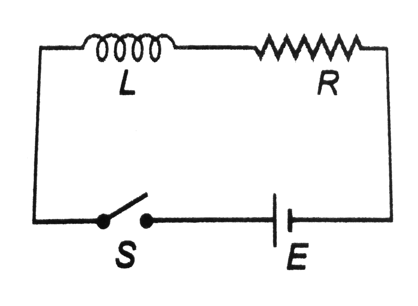
View SolutionIn the circuit shown in figure the switch S is closed at t = 0. A long time after closing the switch
View SolutionIn the circuit shown in figure switch S is closed at time t=0, which statement is true after one time constant of L-R circuit?
View SolutionIn the circuit shown in figure switch S is closed at time t=0
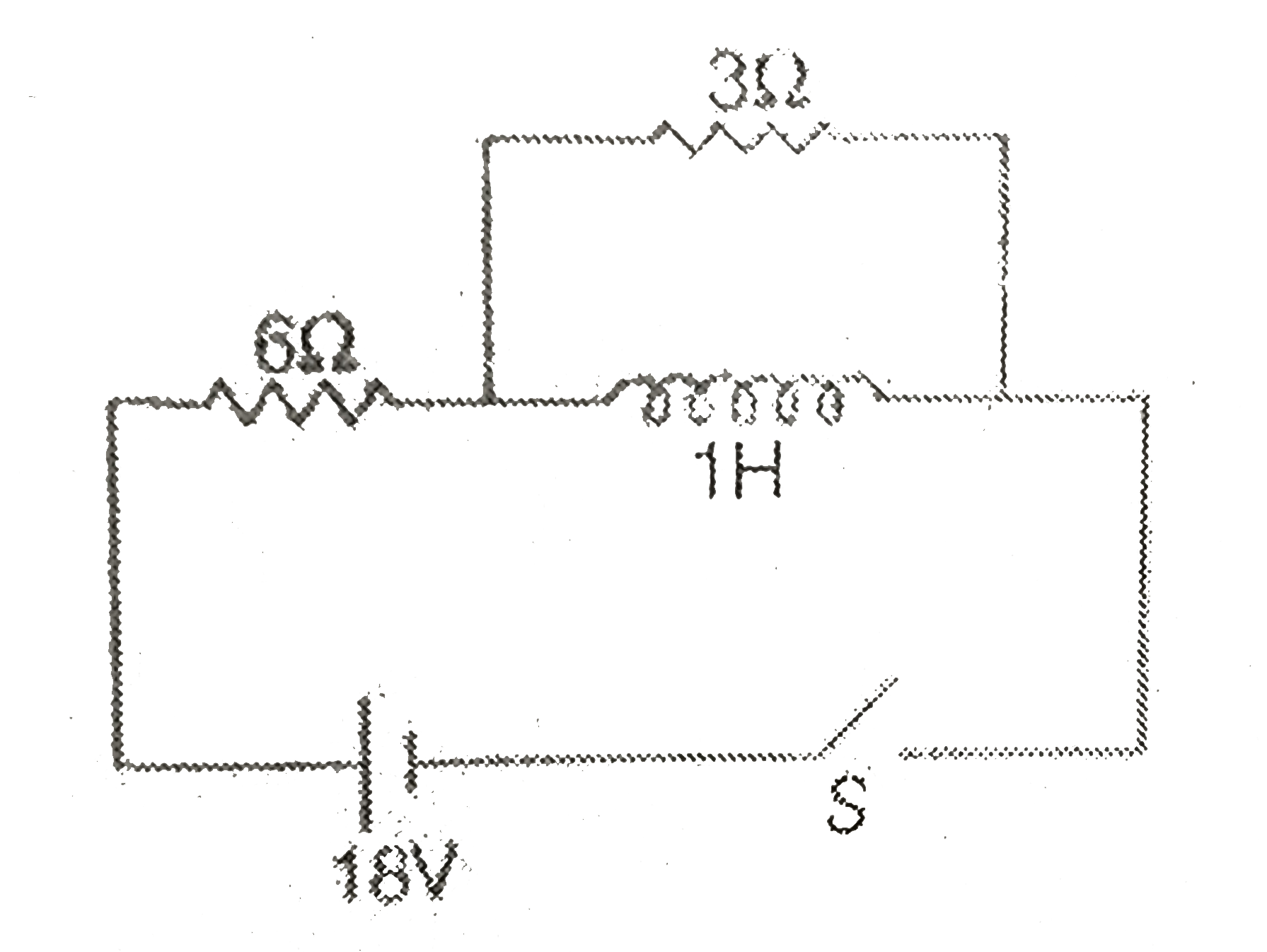
At what time current through 3Ω resistance and 1H inductor are equal?
View Solution
