Draw a circuit diagram which includes the following :
A battery of two cells, a bulb, an open switch.
To draw a circuit diagram that includes a battery of two cells, a bulb, and an open switch, follow these steps:
1. Draw the Battery:
- Start by drawing two cells in series. Each cell is represented by two parallel lines. The longer line represents the positive terminal, and the shorter line represents the negative terminal.
- For two cells, draw one cell above the other. The top cell should have its positive terminal (long line) facing upwards, and the bottom cell should have its positive terminal facing the top cell's negative terminal.
Hint: Remember that cells are drawn with a long line for the positive terminal and a short line for the negative terminal.
2. Connect the Cells:
- Connect the negative terminal of the top cell to the positive terminal of the bottom cell with a straight line. This shows that the cells are connected in series.
Hint: The connection between the cells is crucial to show that they work together as a battery.
3. Draw the Bulb:
- Next, draw the bulb. The symbol for a bulb is a circle with a small line protruding from the bottom. This line represents the connection point.
Hint: Ensure the bulb is drawn clearly so it can be easily identified in the circuit.
4. Connect the Bulb:
- Connect one terminal of the bulb to the negative terminal of the bottom cell with a straight line.
Hint: This connection is where the current will flow to the bulb.
5. Draw the Open Switch:
- Now, draw the open switch. The symbol for an open switch is represented by two lines that are not connected. It looks like a break in the circuit.
Hint: The open switch indicates that the circuit is incomplete, and no current can flow.
6. Connect the Switch:
- Connect the other terminal of the bulb to one terminal of the switch. Then, connect the other terminal of the switch back to the positive terminal of the top cell.
Hint: This completes the circuit diagram, showing how the components are connected.
Final Circuit Diagram:
- The final circuit diagram will show two cells connected in series, a bulb connected to the cells, and an open switch interrupting the circuit.
Summary of the Diagram:
- Two cells in series (battery)
- A bulb connected to the battery
- An open switch that interrupts the circuit
- Start by drawing two cells in series. Each cell is represented by two parallel lines. The longer line represents the positive terminal, and the shorter line represents the negative terminal.
- For two cells, draw one cell above the other. The top cell should have its positive terminal (long line) facing upwards, and the bottom cell should have its positive terminal facing the top cell's negative terminal.
- Connect the negative terminal of the top cell to the positive terminal of the bottom cell with a straight line. This shows that the cells are connected in series.
- Next, draw the bulb. The symbol for a bulb is a circle with a small line protruding from the bottom. This line represents the connection point.
- Connect one terminal of the bulb to the negative terminal of the bottom cell with a straight line.
- Now, draw the open switch. The symbol for an open switch is represented by two lines that are not connected. It looks like a break in the circuit.
- Connect the other terminal of the bulb to one terminal of the switch. Then, connect the other terminal of the switch back to the positive terminal of the top cell.
- The final circuit diagram will show two cells connected in series, a bulb connected to the cells, and an open switch interrupting the circuit.
- Two cells in series (battery)
- A bulb connected to the battery
- An open switch that interrupts the circuit
Topper's Solved these Questions
Similar Questions
Knowledge Check
In the following circuit diagram, the current through battery is
 A4AB3AC1AD2A
Draw a schematic diagram of an electric circuit consisting of a battery of two cells each of 1.5V, 5Ω,10Ω,15Ω resistors and a plug key, all connected in series.
View SolutionIn the circuit diagram shown in figure match the following two columns when switch S is closed.

View SolutionDraw a circuit diagram to show how 3 bulbs can be lit from a battery so that 2 bulbs are controlled by the same switch while the third bulb has its own switch.
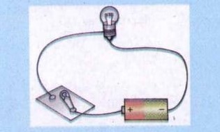
View SolutionDraw the circuit diagram to represent the circuit shown below.

View SolutionDraw circuit symbols for (a) fixed resistance (b) variable resistance (c) a cell (d) a battery of three cells (e) an open switch (f) a closed switch.
View SolutionDraw the electrical symbols for
an open switch.
View SolutionDraw a circuit diagram to show biasing of a solar cell. Draw its characteristic curve and explain it
View Solution
