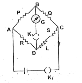
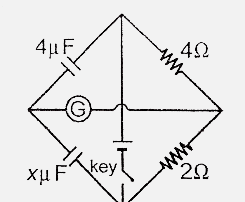
Two inductors of self inductances L1andL2 and of resistances R1andR2 (not shown) respectively are conneted in the circuit as shown. At the instant t = 0, key k is closed. Obtain an expression for which the galvanometer will show zero deflection at all times after the key is closed.
To solve the problem, we need to derive the condition under which the galvanometer shows zero deflection after the key is closed. This means that the current through the galvanometer must remain constant, implying that the net voltage across it must also remain constant.
1. Understanding the Circuit:
- We have two inductors with self-inductances L1 and L2, and resistances R1 and R2 (not shown in the figure).
- When the key K is closed at t=0, current begins to flow through the circuit.
2. Applying Kirchhoff’s Voltage Law (KVL):
- For the loop containing L1 and R1:
VAB=L1dI1dt+I1R1
- For the loop containing L2 and R2:
VBC=L2dI2dt+I2R2
- Since the galvanometer shows zero deflection, we have:
VAB=VAD
VBC=VBD
3. Setting Up the Equations:
- From the above equations, we can equate the voltages:
L1dI1dt+I1R1=L2dI2dt+I2R2
- Additionally, we can relate the currents through the resistors:
I1R3=I2R4
4. Substituting and Rearranging:
- Substitute I1 in terms of I2 using the relation I1=R4R3I2:
L1dI1dt+(R4R3I2)R1=L2dI2dt+I2R2
- Rearranging gives:
L1dI1dt=L2dI2dt+I2R2−R4R3I2R1
5. Condition for Zero Deflection:
- For the galvanometer to show zero deflection, the change in current must be zero, implying:
dI2dt=0
- This leads to the condition:
L1L2=R3R4=R1R2
Final Expression:
Thus, the condition for which the galvanometer will show zero deflection at all times after the key is closed is:
L1L2=R3R4=R1R2
- We have two inductors with self-inductances L1 and L2, and resistances R1 and R2 (not shown in the figure).
- When the key K is closed at t=0, current begins to flow through the circuit.
- For the loop containing L1 and R1:
VAB=L1dI1dt+I1R1
- For the loop containing L2 and R2:
VBC=L2dI2dt+I2R2
- Since the galvanometer shows zero deflection, we have:
VAB=VAD
VBC=VBD
- From the above equations, we can equate the voltages:
L1dI1dt+I1R1=L2dI2dt+I2R2
- Additionally, we can relate the currents through the resistors:
I1R3=I2R4
- Substitute I1 in terms of I2 using the relation I1=R4R3I2:
L1dI1dt+(R4R3I2)R1=L2dI2dt+I2R2
- Rearranging gives:
L1dI1dt=L2dI2dt+I2R2−R4R3I2R1
- For the galvanometer to show zero deflection, the change in current must be zero, implying:
dI2dt=0
- This leads to the condition:
L1L2=R3R4=R1R2
Thus, the condition for which the galvanometer will show zero deflection at all times after the key is closed is:
L1L2=R3R4=R1R2
Topper's Solved these Questions
- ELECTROMAGNETIC INDUCTIONBOOK - AAKASH INSTITUTE ENGLISHCHAPTER - ELECTROMAGNETIC INDUCTIONEXERCISE - EXERCISE
30 Videos
- ELECTROMAGNETIC INDUCTIONBOOK - AAKASH INSTITUTE ENGLISHCHAPTER - ELECTROMAGNETIC INDUCTIONEXERCISE - ASSIGNMENT(SECTION - A) (OBJECTIVE TYPE QUESTIONS)
35 Videos
- ELECTROMAGNETIC INDUCTIONBOOK - AAKASH INSTITUTE ENGLISHCHAPTER - ELECTROMAGNETIC INDUCTIONEXERCISE - Assignment (SECTION - I)
6 Videos
- ELECTRIC CHARGES AND FIELDS BOOK - AAKASH INSTITUTE ENGLISHCHAPTER - ELECTRIC CHARGES AND FIELDS EXERCISE - comprehension
3 Videos
- ELECTROMAGNETIC WAVESBOOK - AAKASH INSTITUTE ENGLISHCHAPTER - ELECTROMAGNETIC WAVESEXERCISE - ASSIGNMENT SECTION - D Assertion-Reason Type Questions
25 Videos
Similar Questions
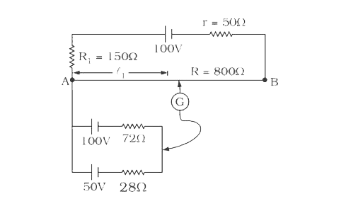
In the circuit shown, the length of AB is 100 cm. The lengthj1 for which the galvanometer shows zero deflection is __________ cm.
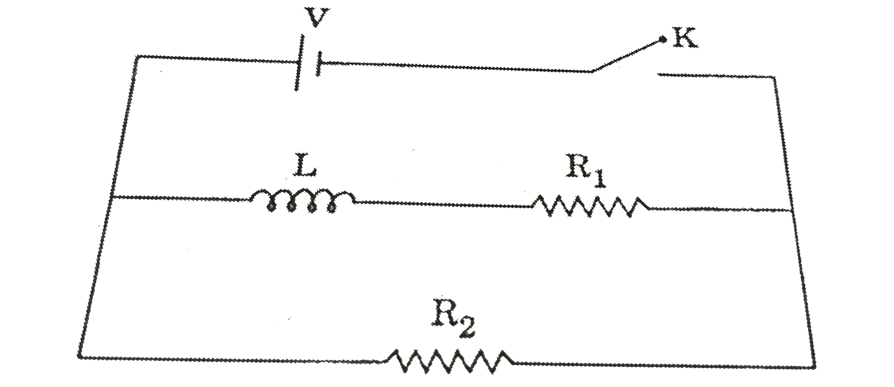
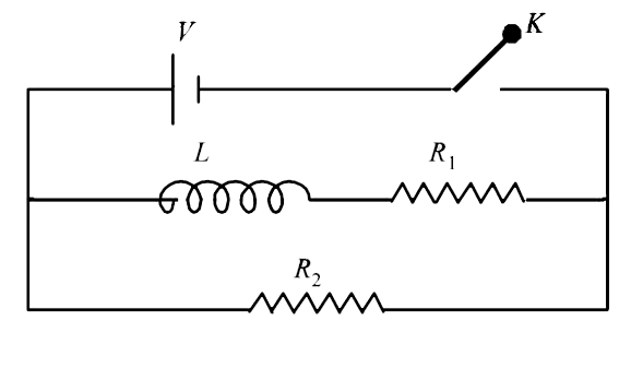
View SolutionIn the circuit shown below, the key K is closed at t = 0. The current through the battery is
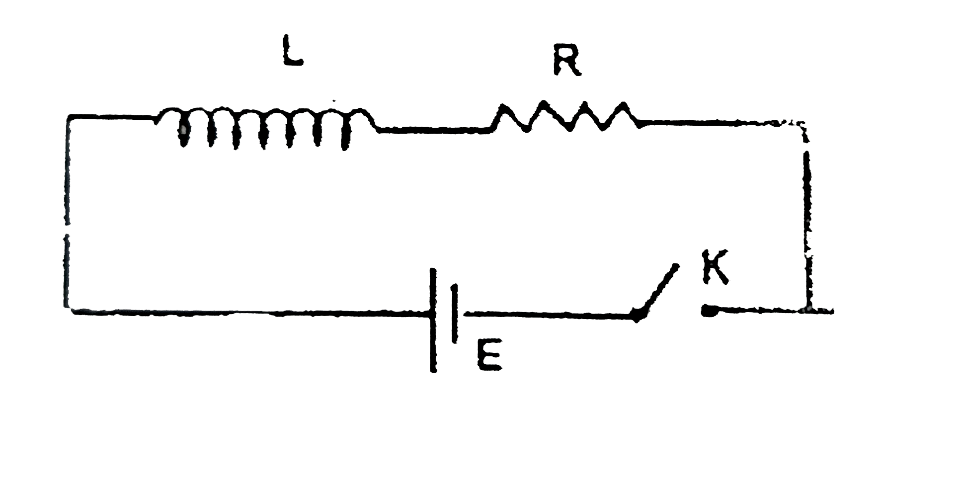
View SolutionShown in the figure is an R−L circuit. Just after the key (K) is closed
View SolutionA circuit contains two inductors of self-inductance L1 and L2 in series (Fig) If M is the mutual inductence, then the effective inductance of the circuit shows will be

View SolutionIn the circuit shown below, the key K is closed at t =0. The current through the battery is
View SolutionThe resistances P,Q,R and S in the bridge shown are adjusted such that the deflection in the galvanometer G is zero when both the keys K1 and K2 are inserted. The galvanometer will show a momentary deflection if
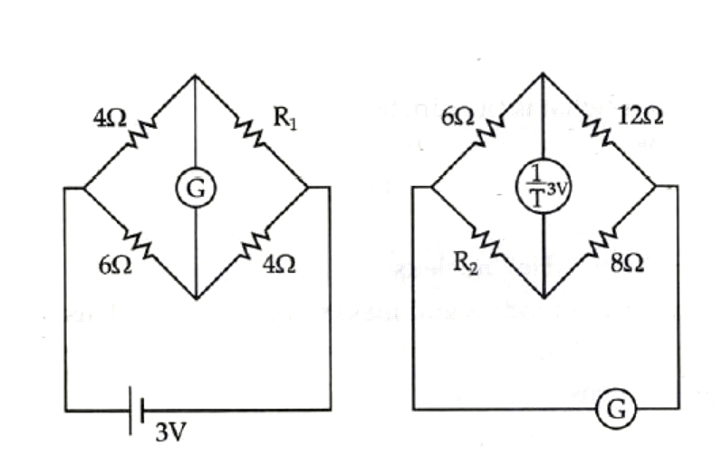
View SolutionIn the circuits shown in the figures, the galvanometers show no deflection. Find the ratio of R1 and R2.
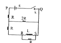
View SolutionIn the figure shown is a R-L circuit connected with a cell of emf ε through a key k. If key k is closed find the current drawn by the battery
(a) just after the key k is closed
(b) long after the key k is closed
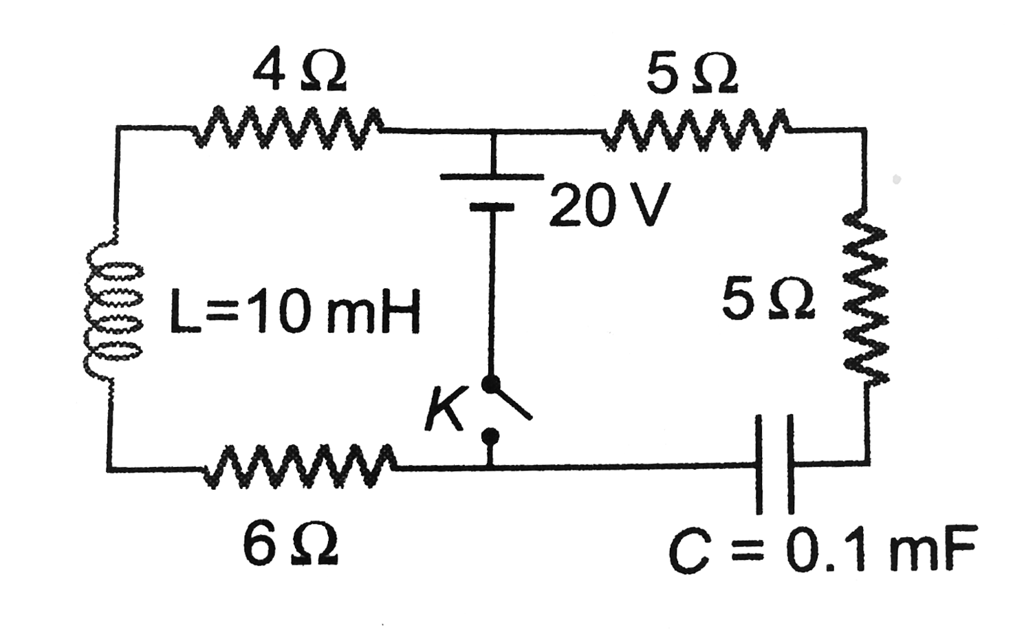
View SolutionIn the circuit shown the key (K) is closed at t=0, the current through the key at the instant t=10−3ln,2 is
View SolutionConsider the circuit shown with key opened . The key is closed at t=0 . Capacitance of one of the shown capacitors is x μF. For what svalue of x the galvanometer does not shown any deflection ?
View Solution
