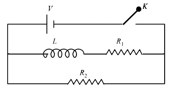
In the circuit shown below, the key K is closed at t =0. The current through the battery is
V(R1+R2)R1+R2at t = 0 andVR2at t=∞
V(R1+R2)√R21+R22at t = 0 andVR2at t=∞
VR2 at t =0 andV(R1+R2)R1R2at t=∞
VR2 at t = 0 and V(R1+R2)√R21+R22 at t=∞
The correct Answer is:C
At t = 0 ionductor behaves as broken wire, then i=VR2.
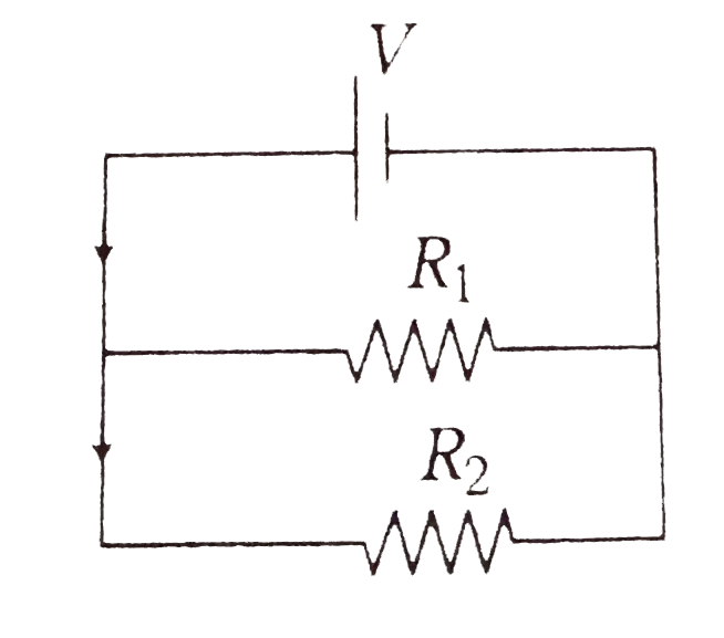
At i=∞, inductor behaves as a conducting wire,
i=VR1R2/(R1+R2)=V(R1+R2)R1R2
Topper's Solved these Questions
- ELECTROMAGNETIC INDUCTIONBOOK - DC PANDEY ENGLISHCHAPTER - ELECTROMAGNETIC INDUCTIONEXERCISE - Medical entrance special format questions
17 Videos
- ELECTROMAGNETIC INDUCTIONBOOK - DC PANDEY ENGLISHCHAPTER - ELECTROMAGNETIC INDUCTIONEXERCISE - Match the columns
5 Videos
- ELECTROMAGNETIC INDUCTIONBOOK - DC PANDEY ENGLISHCHAPTER - ELECTROMAGNETIC INDUCTIONEXERCISE - Check point
60 Videos
- CURRENT ELECTRICITYBOOK - DC PANDEY ENGLISHCHAPTER - CURRENT ELECTRICITYEXERCISE - Medical entrances gallery
97 Videos
- ELECTROMAGNETIC WAVESBOOK - DC PANDEY ENGLISHCHAPTER - ELECTROMAGNETIC WAVESEXERCISE - Sec C
22 Videos
Similar Questions
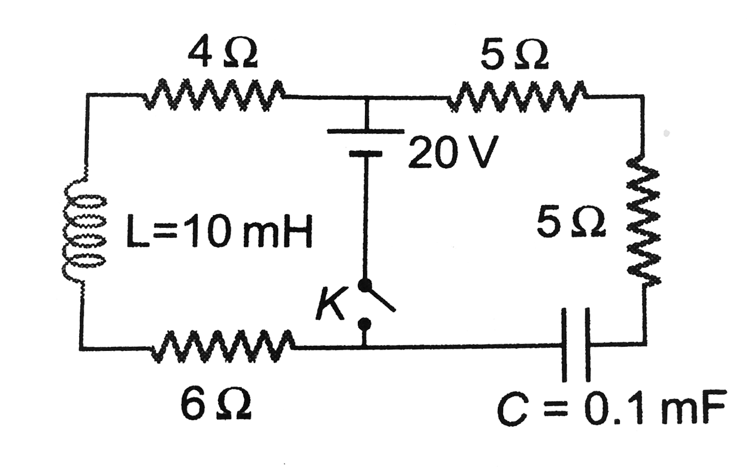
In the circuit shown the key (K) is closed at t=0, the current through the key at the instant t=10−3ln,2 is
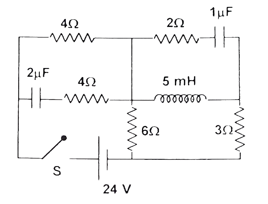
View SolutionIn the circuit shown, the switch 'S' is closed at t=0. Then the current through the battery steady state reached is
View SolutionConsider the circuit shown. Switch is closed at t=0. Find the current through the battery as a function of time. Initially capacitor was uncharged.
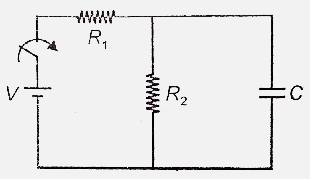
View SolutionIn the circuit shown below, the key is pressed at time t = 0. The correct statement is
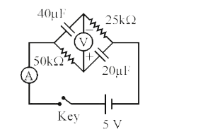
View SolutionIn th circuit the key (K) is closed at t=0. Find the current in ampere through the key (K) at the instant t=102ln2 sec.
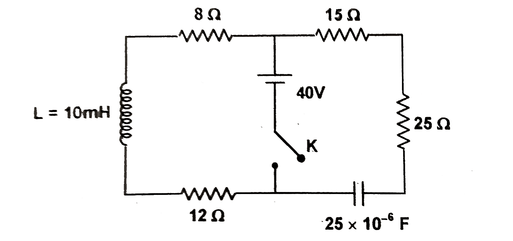
View SolutionIn the circuit shown, switch S is closed at time t=0. Find the current through the inductor as a function of time t.
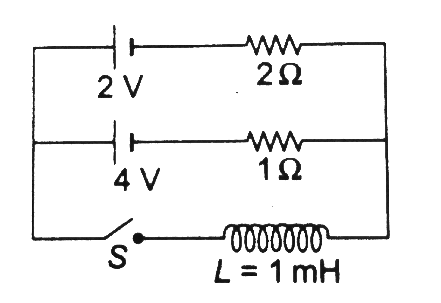
View SolutionIn the circuit shown in figure switch S is closed at time t=0
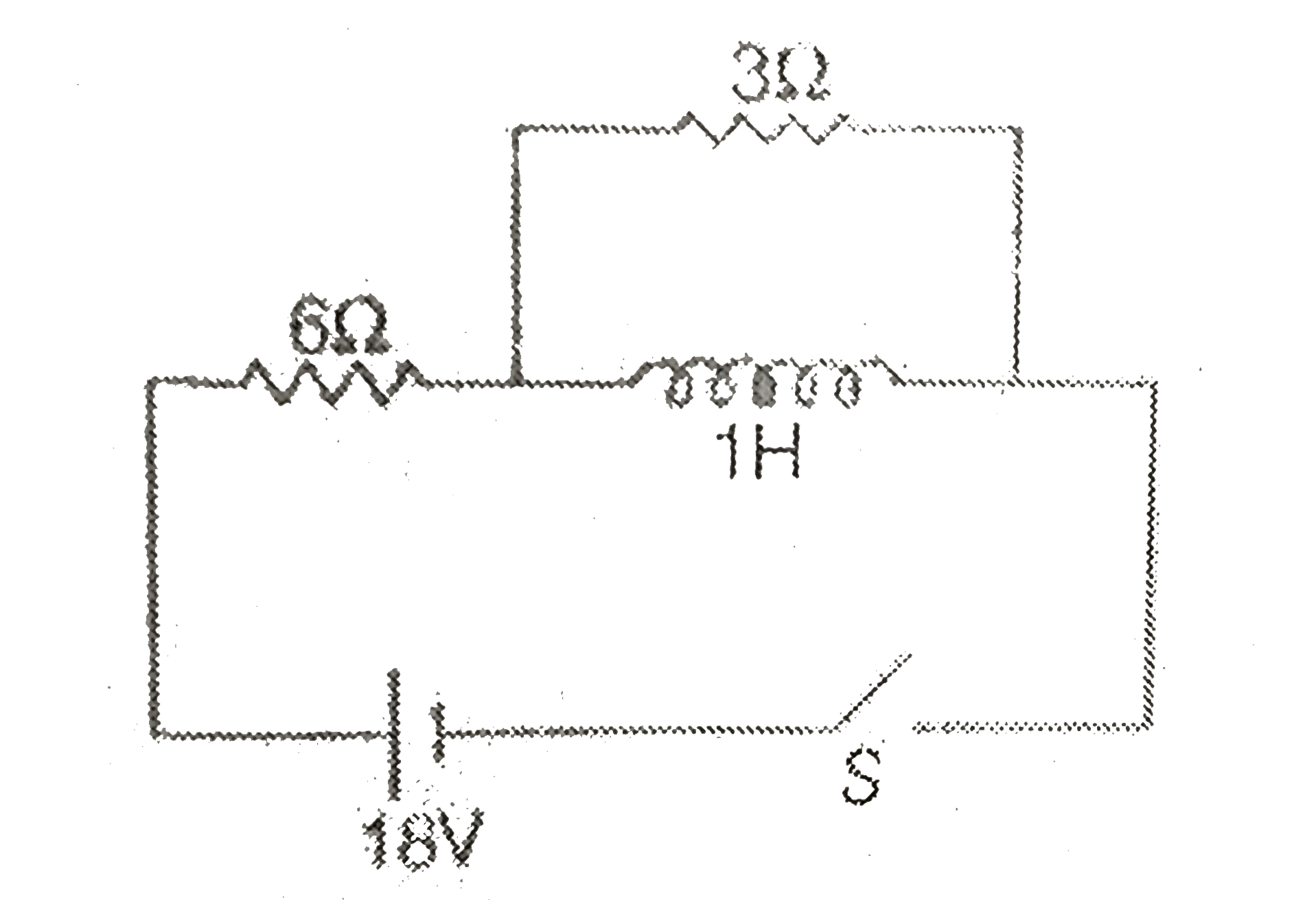
Current I from the battery at time t is given by
View SolutionIn the given circuit,
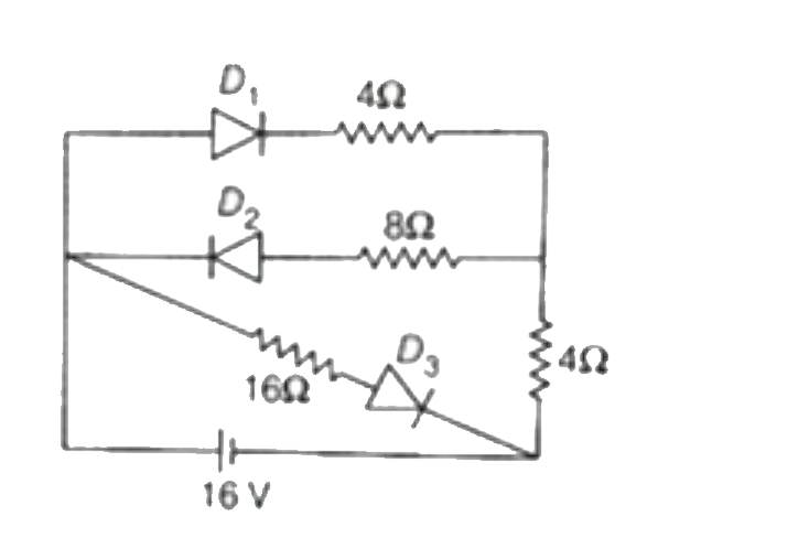
the current through the battery is
View Solutionthere in no current part of this circuit for time t<o. Switch S is closed at t=0.
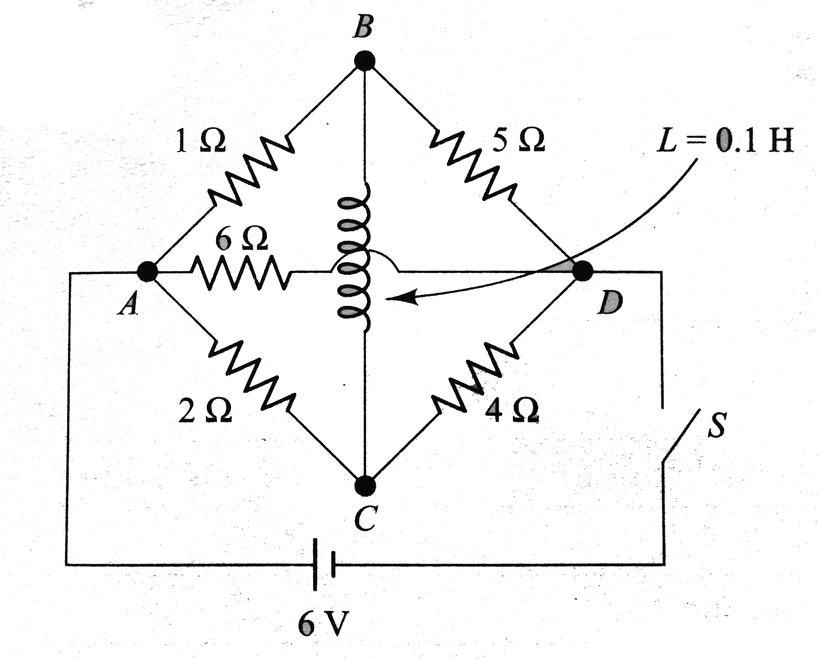
The current through the inductor after a long time will be
View Solution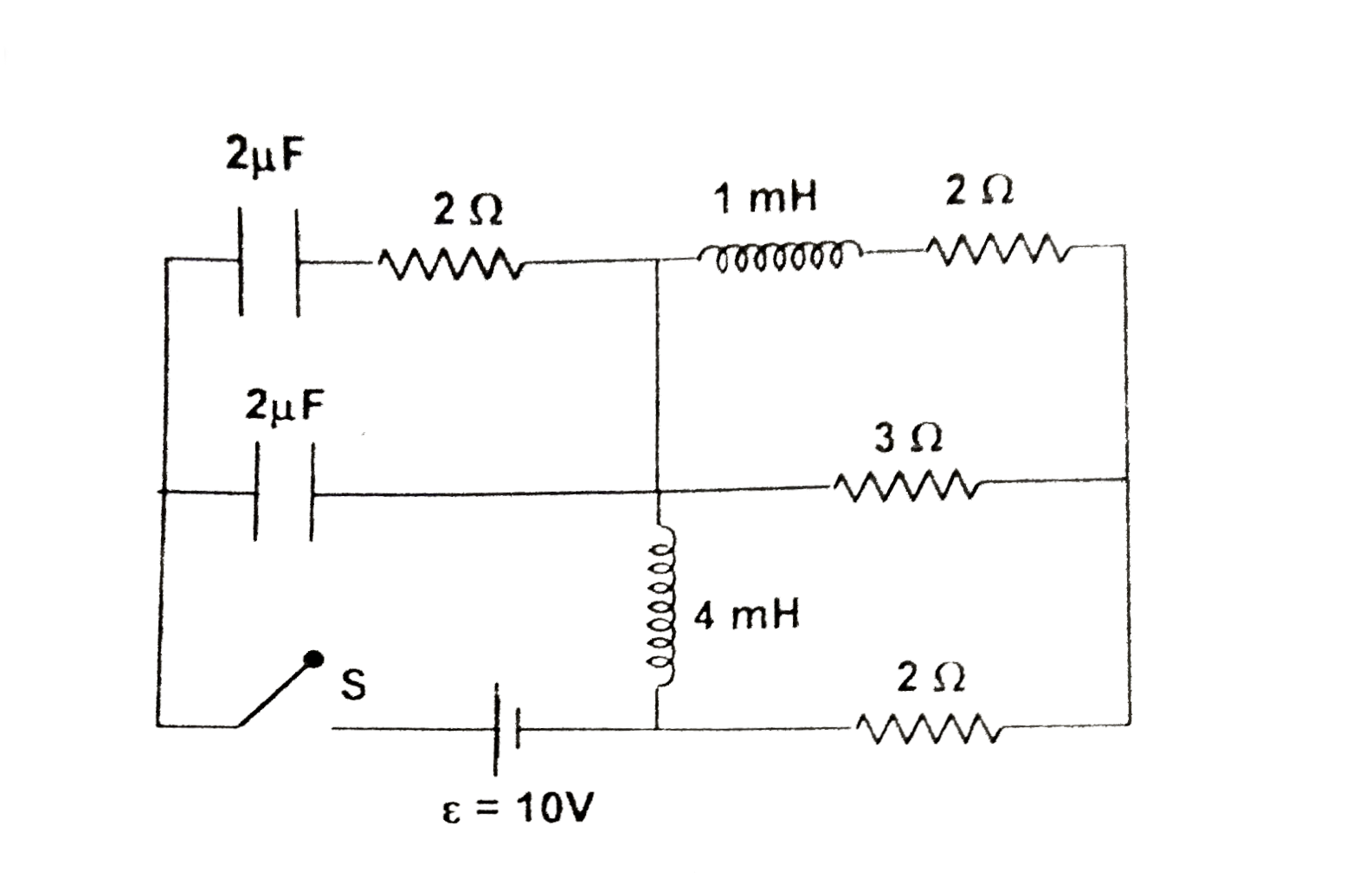
In the circuit shown, all the capacitors are initially uncharged. The current through the battery just after closing the switch 'S' is
View Solution
