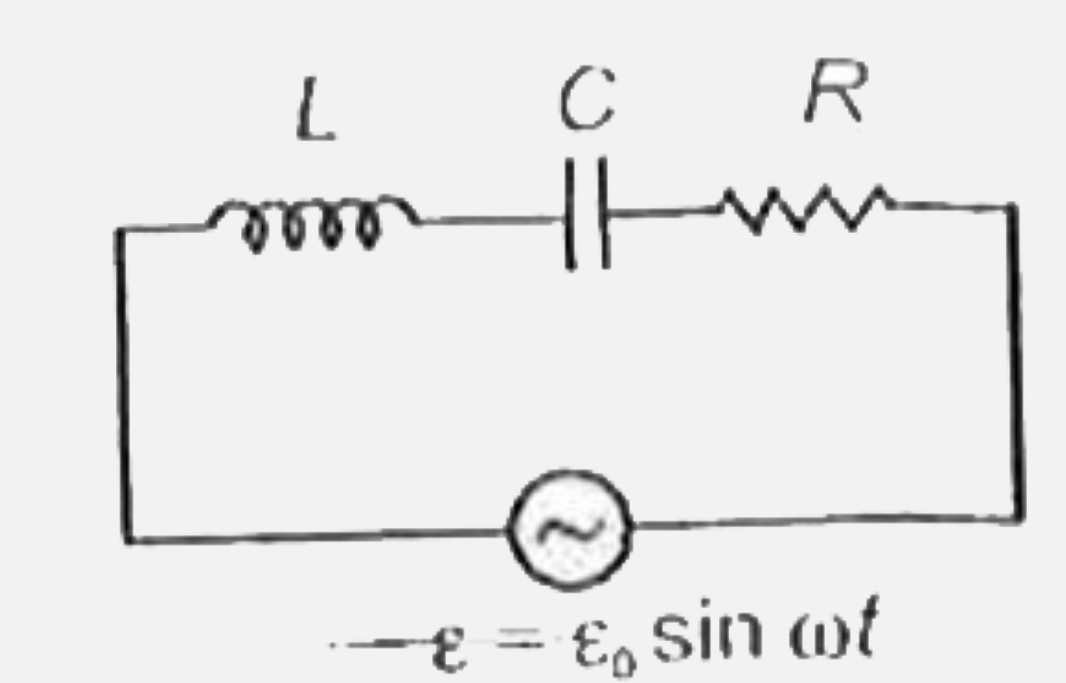
In a circuit, an inductor (L), capacitor (C) and resistor (R) are connected in parallel across a source of emf given by ε=ε0sinωt. Find the current through the mains and draw a phasor diagram.
To solve the problem of finding the current through the mains in a parallel LCR circuit and drawing the corresponding phasor diagram, we will follow these steps:
Step 1: Understand the Circuit
In the given circuit, we have an inductor (L), a capacitor (C), and a resistor (R) connected in parallel across an alternating current source with voltage ϵ=ϵ0sin(ωt). The voltage across each component is the same and equal to the source voltage ϵ.
Step 2: Write the Voltage Across Each Component
The voltage across the inductor (V_L), capacitor (V_C), and resistor (V_R) is given by:
- VL=ϵ
- VC=ϵ
- VR=ϵ
Step 3: Calculate the Current Through Each Component
The current through each component can be expressed as:
- For the resistor:
IR=VRR=ϵR
- For the capacitor:
IC=VCXC=ϵ1ωC=ϵωC
- For the inductor:
IL=VLXL=ϵωL
Step 4: Determine the Phase Relationships
- The current through the resistor IR is in phase with the voltage.
- The current through the capacitor IC leads the voltage by π2.
- The current through the inductor IL lags the voltage by π2.
Step 5: Draw the Phasor Diagram
1. Draw the voltage phasor ϵ along the horizontal axis.
2. Draw the current phasor IR along the same direction as ϵ.
3. Draw the current phasor IC leading ϵ by π2 (90 degrees).
4. Draw the current phasor IL lagging ϵ by π2 (90 degrees).
Step 6: Calculate the Equivalent Current
The equivalent current I through the mains can be found using vector addition:
- The currents IC and IL are in opposite directions, so we can express the resultant current as:
Ieq=IC−IL
- The total current I can be calculated using the Pythagorean theorem since IR is perpendicular to Ieq:
I=√I2R+(IC−IL)2
Step 7: Substitute the Values
Substituting the values of IR, IC, and IL:
I=√(ϵR)2+(ϵωC−ϵωL)2
Step 8: Simplify the Expression
Factoring out ϵ:
I=ϵZ
where Z is the impedance given by:
Z=√R2+(1ωC−ωL)2
Final Result
The final expression for the current through the mains is:
I=ϵZ
In the given circuit, we have an inductor (L), a capacitor (C), and a resistor (R) connected in parallel across an alternating current source with voltage ϵ=ϵ0sin(ωt). The voltage across each component is the same and equal to the source voltage ϵ.
The voltage across the inductor (V_L), capacitor (V_C), and resistor (V_R) is given by:
- VL=ϵ
- VC=ϵ
- VR=ϵ
The current through each component can be expressed as:
- For the resistor:
IR=VRR=ϵR
- For the capacitor:
IC=VCXC=ϵ1ωC=ϵωC
- For the inductor:
IL=VLXL=ϵωL
- The current through the resistor IR is in phase with the voltage.
- The current through the capacitor IC leads the voltage by π2.
- The current through the inductor IL lags the voltage by π2.
1. Draw the voltage phasor ϵ along the horizontal axis.
2. Draw the current phasor IR along the same direction as ϵ.
3. Draw the current phasor IC leading ϵ by π2 (90 degrees).
4. Draw the current phasor IL lagging ϵ by π2 (90 degrees).
The equivalent current I through the mains can be found using vector addition:
- The currents IC and IL are in opposite directions, so we can express the resultant current as:
Ieq=IC−IL
- The total current I can be calculated using the Pythagorean theorem since IR is perpendicular to Ieq:
I=√I2R+(IC−IL)2
Substituting the values of IR, IC, and IL:
I=√(ϵR)2+(ϵωC−ϵωL)2
Factoring out ϵ:
I=ϵZ
where Z is the impedance given by:
Z=√R2+(1ωC−ωL)2
The final expression for the current through the mains is:
I=ϵZ
Topper's Solved these Questions
- BOOK - AAKASH INSTITUTE ENGLISHCHAPTER - ALTERNATING CURRENT EXERCISE - Try Yourself15videos
ALTERNATING CURRENT
- BOOK - AAKASH INSTITUTE ENGLISHCHAPTER - ALTERNATING CURRENT EXERCISE - Assignment (Section - A) ( Objective Type Questions ( One option is correct))40videos
ALTERNATING CURRENT
- BOOK - AAKASH INSTITUTE ENGLISHCHAPTER - ATOMSEXERCISE - ASSIGNMENT SECTION J (Aakash Challengers )5videos
ATOMS
Similar Questions
A series LCR circuit consists of an inductor L a capacitor C and a resister R connected across a source of emfε=ε0sinωt. When ωL=1ωC the current in the circuit is l0 and if angular frequency of the source is changed to ω, the current in the circuit becoms (l02 then the value of ∣∣∣ω'L−1ω'C∣∣∣ is
 View Solution
A satellite is launched into a circular orbit of radius R around the earth while a second satellite is launched into an orbit of radius 1.02R. The percentage difference in the time period is:
View SolutionAn inductor 20×10−3 a capacitor 100(μ)F and a resistor 50Ω are connected in series across a source of emf V=10sin314t.
Then the energy dissipated in the circuit in 20 mim isView SolutionAn inductor 20mH, a capacitor 50μF and a resistor 40Ωare connected in series across of emf V=10sin340t. The power loss in A.C. circuit is
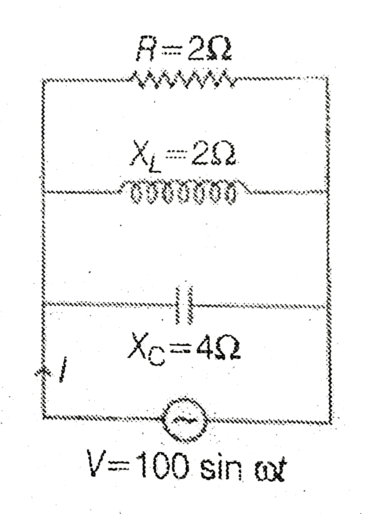
View SolutionResistor, inductor and capacitor are connected in parallel to an AC source of emf V=100sinωt If R=2Ω,XL=2ΩandXC=4Ω,, then choose correct option:
 View Solution
An inductor 20×10−3 a capacitor 100(μ)F and a resistor 50Ω are connected in series across a source of emf V=10sin314t.
If resistance is removed from the circuit and the value of inductance is doubled, the variation of current with time in the new circuit isView SolutionAn inductor 2/π Henry, a capacitor 100/TμF and a resistor 75Ω are connected in series across a source of emf V=10sin100πt. Here t is in second. (a) find the impedance of the circuit. (b) find the energy dissipated in the circuit in 20 minutes.
View SolutionAn inductor and resistor are connected in series across A.C supply which of the following phasor diagram may be correct?
View SolutionTwo coils of self inductance L1 and L2 are connected in parallel and then connected to a cell of emf ε and internal resistance - R. Find the steady state current in the coils.
View SolutionIn the circuit diagram shown in find the current through the 1Ω resistor.
 View Solution

