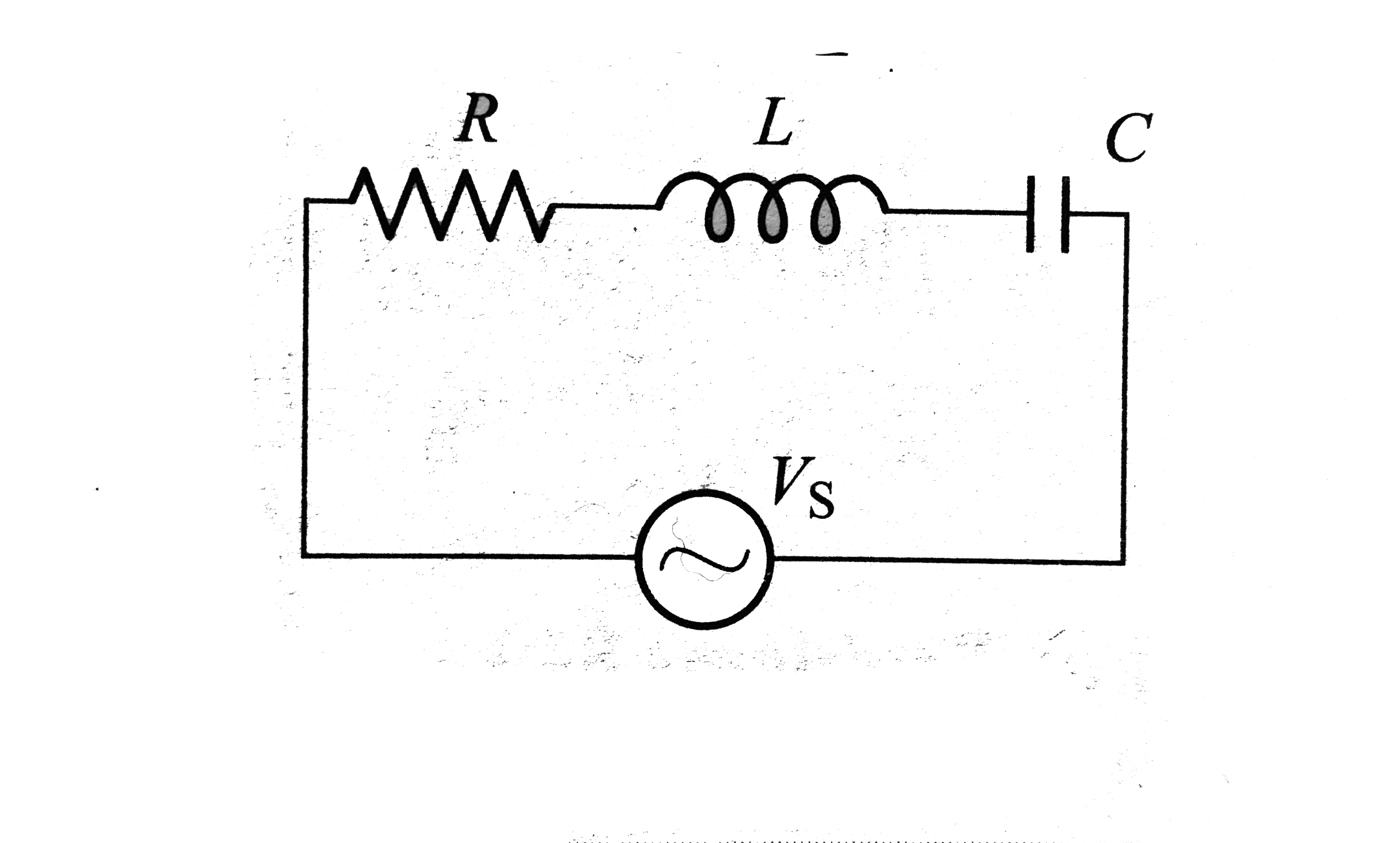
In a series LCR circuit, the the rms voltage supply is 170 V. If VR,VLandVC represent the rms voltage drop across resistor , inductor and capacitor, then
VR≤170V (always)
VL≥170V (always)
VLorVC may be greater than 170 V
|VL−VC|<170
The correct Answer is:A, C, D
To solve the problem regarding the series LCR circuit with an RMS voltage supply of 170 V, we will analyze the relationships between the RMS voltage drops across the resistor (V_R), inductor (V_L), and capacitor (V_C).
1. Understanding the Phasor Diagram:
In a series LCR circuit, the voltage across the resistor (V_R) is in phase with the current, while the voltages across the inductor (V_L) and capacitor (V_C) are out of phase with the current. The phasor diagram shows V_R along the horizontal axis, V_L upwards, and V_C downwards.
2. Applying Kirchhoff's Voltage Law:
According to Kirchhoff's law, the total voltage in the circuit is given by:
V=VR+(VL−VC)
However, since V_L and V_C are out of phase, we need to consider their vector nature.
3. Using the Pythagorean Theorem:
The effective voltage (V) in the circuit can be expressed as:
V2=V2R+(VL−VC)2
Given that the RMS voltage supply is 170 V, we have:
1702=V2R+(VL−VC)2
4. Deriving Relationships:
- For V_R: Since V2R and (VL−VC)2 are both positive, it follows that:
V2R≤1702⟹VR≤170 V
- For V_L and V_C: The difference VL−VC can also be analyzed. If we set VR=0, we find:
1702=(VL−VC)2⟹|VL−VC|=170 V
This means that either VL or VC can be greater than 170 V, depending on their values.
5. Conclusion:
- VR≤170 V (always true)
- VL or VC can be greater than 170 V (possible)
- The difference VL−VC can vary, but it can be less than or equal to 170 V depending on the values of VL and VC.
Summary of Relationships:
1. VR≤170
2. VL or VC may be greater than 170.
3. VL−VC can be less than or equal to 170.
In a series LCR circuit, the voltage across the resistor (V_R) is in phase with the current, while the voltages across the inductor (V_L) and capacitor (V_C) are out of phase with the current. The phasor diagram shows V_R along the horizontal axis, V_L upwards, and V_C downwards.
According to Kirchhoff's law, the total voltage in the circuit is given by:
V=VR+(VL−VC)
However, since V_L and V_C are out of phase, we need to consider their vector nature.
The effective voltage (V) in the circuit can be expressed as:
V2=V2R+(VL−VC)2
Given that the RMS voltage supply is 170 V, we have:
1702=V2R+(VL−VC)2
- For V_R: Since V2R and (VL−VC)2 are both positive, it follows that:
V2R≤1702⟹VR≤170 V
- For V_L and V_C: The difference VL−VC can also be analyzed. If we set VR=0, we find:
1702=(VL−VC)2⟹|VL−VC|=170 V
This means that either VL or VC can be greater than 170 V, depending on their values.
- VR≤170 V (always true)
- VL or VC can be greater than 170 V (possible)
- The difference VL−VC can vary, but it can be less than or equal to 170 V depending on the values of VL and VC.
1. VR≤170
2. VL or VC may be greater than 170.
3. VL−VC can be less than or equal to 170.
Topper's Solved these Questions
- BOOK - AAKASH INSTITUTE ENGLISHCHAPTER - ALTERNATING CURRENT EXERCISE - Assignment (Section - D) (Linked Comprehension Type Questions)3videos
ALTERNATING CURRENT
- BOOK - AAKASH INSTITUTE ENGLISHCHAPTER - ALTERNATING CURRENT EXERCISE - Assignment (Section - E) (Assertion-Reason Type Questions)2videos
ALTERNATING CURRENT
- BOOK - AAKASH INSTITUTE ENGLISHCHAPTER - ALTERNATING CURRENT EXERCISE - Assignment (Section - B) (Objective Type Questions (One option is correct))14videos
ALTERNATING CURRENT
- BOOK - AAKASH INSTITUTE ENGLISHCHAPTER - ATOMSEXERCISE - ASSIGNMENT SECTION J (Aakash Challengers )5videos
ATOMS
Similar Questions
In an LCR series ac circuit the voltage across L,C and R are V1,V2 and V3 respectively The voltage of the source is .
View SolutionAn LCR series circuit is connected to an oscillator (AC supply) having RMS voltage 200 V. If the RMS voltages across resistor, inductor and capacitor are equal, then RMS voltage across the resistor would be
View SolutionA series L-C-R circuit is connected across a variable frequency source of emf. VL,VC,VR are instantaneous voltage drops across inductor capacitor and resistor and V is instantaneous voltage across the circuit.
Column I Column II(A)|V|(p)Can be greater than zero(B)|V|−|VL|(q)Can be less than zero(C)|V|−|VC|(r)Can be equal to zero(D)|V|−|VR|View SolutionIn a series L−C circuit, the applied voltage is V0. if omega is very low, then the voltage drop across the inductor VL and capacitor VC are
 .View Solution
in a series LCR circuit, what is the phase difference between VLandVC where VL is the potential difference across the inductor and VC is the potential difference across the capacitor?
View SolutionIn series LCR circuit voltage drop across resistance is 8V, across inductor is 6V and across capacitor is 12V. Then
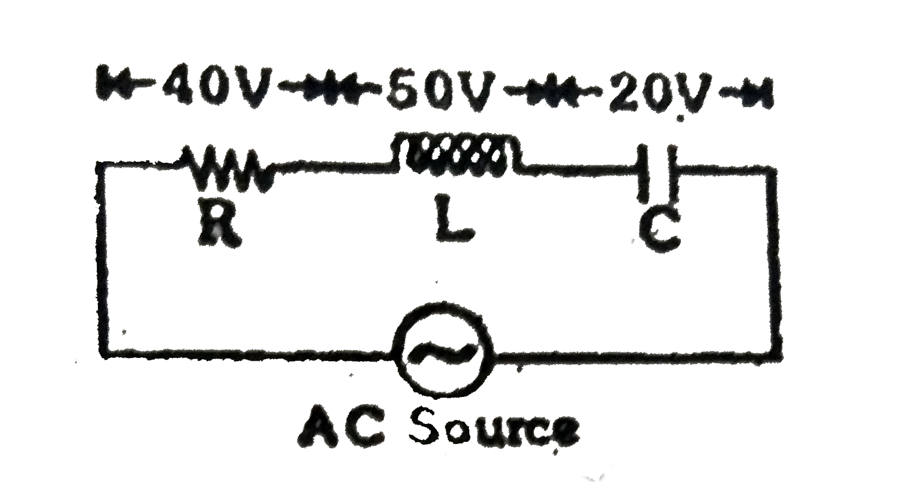
View SolutionIn series LCR circuit, the voltages across R, L and C are shown in the figure. The voltage of applied source
 View Solution
Consider a series LCR circuit connected to an AC supply of 220V. If voltage drop across resistance R is VR, voltage drop across capacitor is Vc=2VR and that across inudctor coil is VL=2VR then choose correct alternative(s)
View SolutionStatement 1: In a series RLC circuit if (VR),(VL)and(VC) denote rms voltage across R,L and C respectively and (VS) is the rms voltage across the source. Then (Vs)=(VR)+(VL)+(VC)
Statement 2: In ac circuit, Kirchhoff's voltage law is correct at every instant of same.
 View Solution
In a series L.C.R. circuit, the potential drop across L, C and R respectively are 40V, 120V and 60V . Them the source voltage is
View Solution

