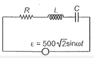
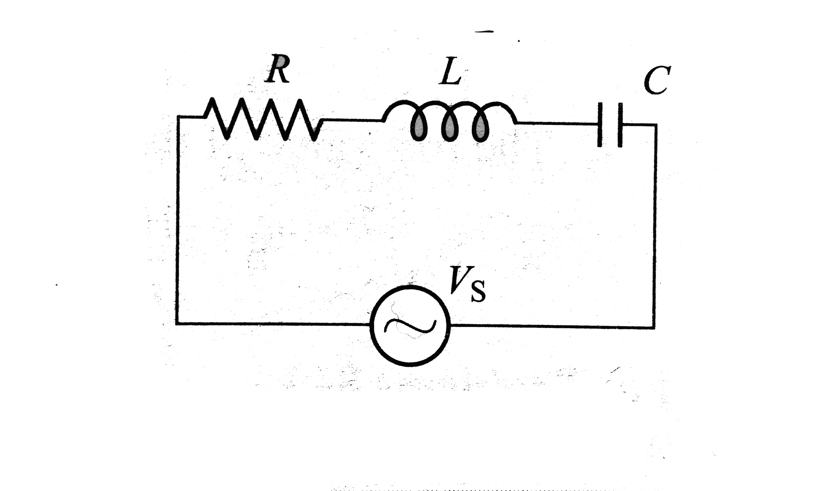
In a series L.C.R. circuit, the potential drop across L, C and R respectively are 40V, 120V and 60V . Them the source voltage is
220 V
160 V
180 V
100 V
The correct Answer is:D
To find the source voltage in a series LCR circuit where the potential drops across the inductor (L), capacitor (C), and resistor (R) are given as 40V, 120V, and 60V respectively, we can follow these steps:
1. Identify the given values:
- Voltage across the inductor (VL) = 40V
- Voltage across the capacitor (VC) = 120V
- Voltage across the resistor (VR) = 60V
2. Understand the phase relationships:
- In an LCR circuit, the voltage across the inductor (VL) leads the current by 90 degrees.
- The voltage across the capacitor (VC) lags the current by 90 degrees.
- The voltage across the resistor (VR) is in phase with the current.
3. Set up the phasor diagram:
- The voltage across the resistor (VR) is along the horizontal axis (real axis).
- The voltage across the inductor (VL) is represented as a vertical vector pointing upwards (imaginary axis).
- The voltage across the capacitor (VC) is represented as a vertical vector pointing downwards (imaginary axis).
4. Calculate the net voltage across the inductor and capacitor:
- The effective voltage across the inductor and capacitor can be calculated as:
VLC=VL−VC=40V−120V=−80V
- Since this is a phasor addition, we consider the magnitude:
|VLC|=80V
5. Use the Pythagorean theorem to find the source voltage (V):
- The source voltage is given by the vector sum of the voltages across the resistor and the effective voltage across the inductor and capacitor:
V=√V2R+V2LC
- Substituting the values:
V=√(60V)2+(80V)2
V=√3600+6400=√10000=100V
6. Conclusion:
- The source voltage is 100V.
Final Answer:
The source voltage is 100V.
---
- Voltage across the inductor (VL) = 40V
- Voltage across the capacitor (VC) = 120V
- Voltage across the resistor (VR) = 60V
- In an LCR circuit, the voltage across the inductor (VL) leads the current by 90 degrees.
- The voltage across the capacitor (VC) lags the current by 90 degrees.
- The voltage across the resistor (VR) is in phase with the current.
- The voltage across the resistor (VR) is along the horizontal axis (real axis).
- The voltage across the inductor (VL) is represented as a vertical vector pointing upwards (imaginary axis).
- The voltage across the capacitor (VC) is represented as a vertical vector pointing downwards (imaginary axis).
- The effective voltage across the inductor and capacitor can be calculated as:
VLC=VL−VC=40V−120V=−80V
- Since this is a phasor addition, we consider the magnitude:
|VLC|=80V
- The source voltage is given by the vector sum of the voltages across the resistor and the effective voltage across the inductor and capacitor:
V=√V2R+V2LC
- Substituting the values:
V=√(60V)2+(80V)2
V=√3600+6400=√10000=100V
- The source voltage is 100V.
The source voltage is 100V.
Similar Questions
In a series LCR circuit the rms voltage across the inductance , capacitance and resistance are respectively 4 V, 8 V and 5 V . The RMS voltage of the AC source in the circuit is
View SolutionIn a series RLC circuit, potential differences across R, L and C are 30 V, 60 V and 100 V respectively as shown in figure. The e.m.f. of source (in volts) is

View Solution
Knowledge Check
In a series LCR circuit the voltage across an inductor, capacitor and resistor are 20 V, 20 V and 40 V respectively. The phase difference between the applied voltage and the current in the circuit is
A30∘B45∘C60∘D0∘
In a series RLC circuit the r.m.s. voltage across the resistor and the inductor are respectively 400 V and 700 V. If the equation for the applied Voltage is ε=500√2sinωt. then the peak voltage across the capacitor is

View SolutionIn an LCR series ac circuit the voltage across L,C and R are V1,V2 and V3 respectively The voltage of the source is .
View SolutionStatement 1: In a series RLC circuit if (VR),(VL)and(VC) denote rms voltage across R,L and C respectively and (VS) is the rms voltage across the source. Then (Vs)=(VR)+(VL)+(VC)
Statement 2: In ac circuit, Kirchhoff's voltage law is correct at every instant of same.

View SolutionIn series LCR circuit, the phase difference between voltage across L and voltage across C is
View SolutionIn a series LCR circuit, the voltages across an inductor, a capacitor and a resistor are 30 V, 30 V, 60 V respectively. What is the phase difference between the applied voltage and the current in the circuit ?
View SolutionIn a series LCR circuit, the voltages across an inductor, a capacitor and a resistor are 30 V, 30 V, 60 V respectively. What is the phase difference between the applied voltage and the current in the circuit ?
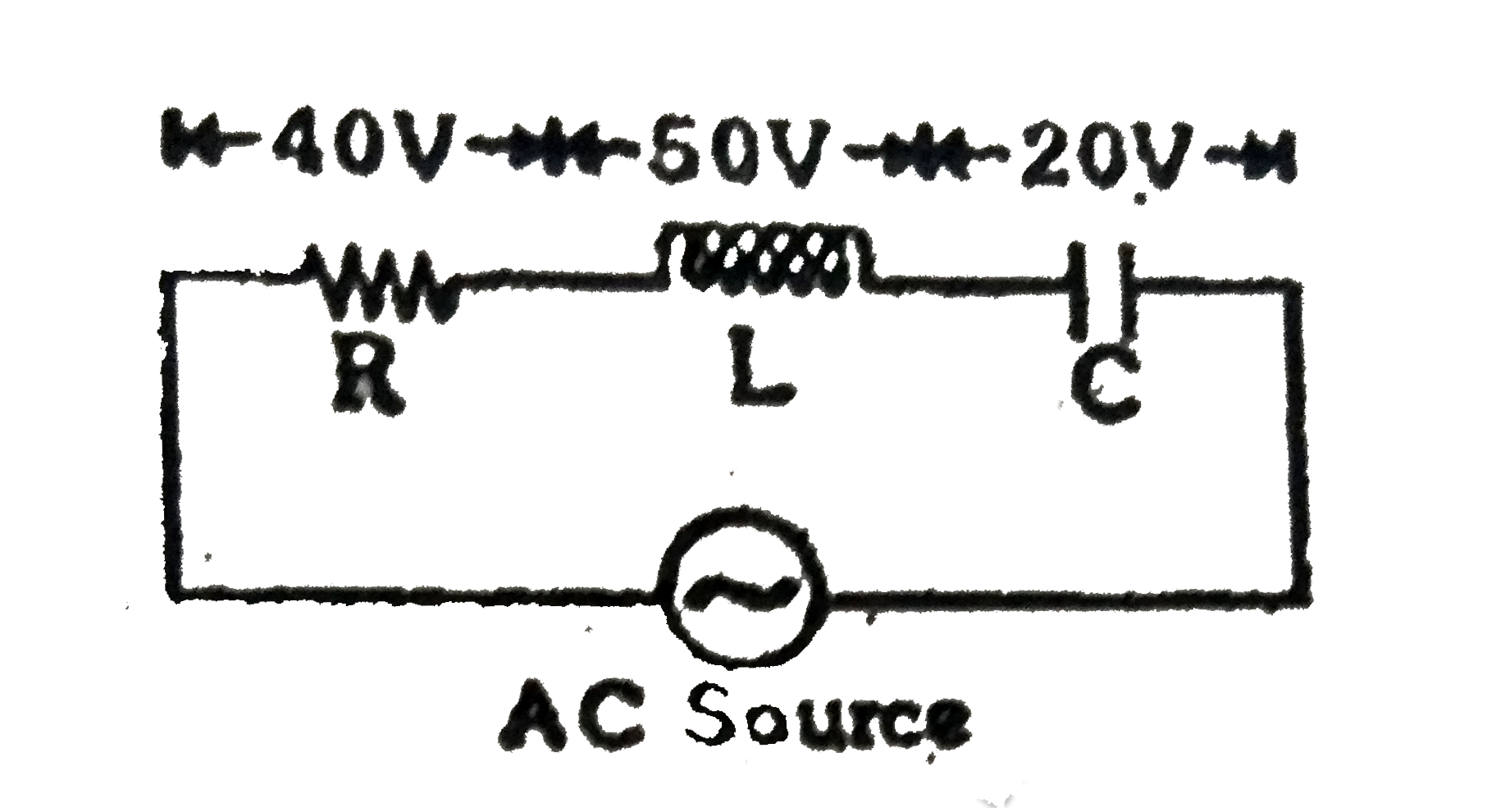
View SolutionIn series LCR circuit, the voltages across R, L and C are shown in the figure. The voltage of applied source

View Solution
