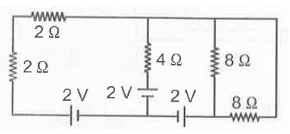
The given circuit is the part of a certain circuit. The current through resistors are shown . The potential difference VP−VQ is
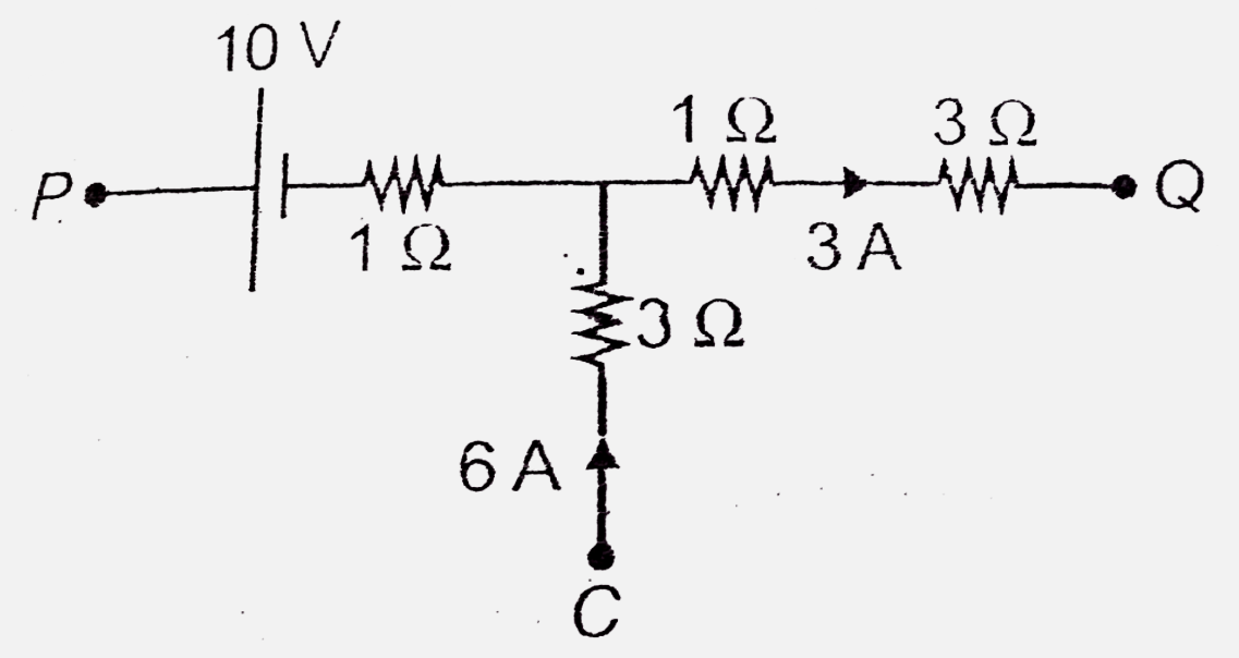
−2V
19V
22V
−19V
The correct Answer is:2
Step by step video & image solution for The given circuit is the part of a certain circuit. The current through resistors are shown . The potential difference V_(P) -V_(Q) is by Physics experts to help you in doubts & scoring excellent marks in Class 12 exams.
Updated on:21/07/2023Topper's Solved these Questions
- CURRENT ELECTRICITYBOOK - AAKASH INSTITUTE ENGLISHCHAPTER - CURRENT ELECTRICITYEXERCISE - ASSIGNMENT SECTION-C(OBJECTIVE TYPE QUESTION ))
13 Videos
- CURRENT ELECTRICITYBOOK - AAKASH INSTITUTE ENGLISHCHAPTER - CURRENT ELECTRICITYEXERCISE - ASSIGNMENT SECTION-D( LINKED COMPREHENSION TYPE QUESTIONS)
3 Videos
- CURRENT ELECTRICITYBOOK - AAKASH INSTITUTE ENGLISHCHAPTER - CURRENT ELECTRICITYEXERCISE - ASSIGNMENT(SECTION-A(OBJECTIVE TYPE QUESTIONS))
69 Videos
- COMMUNICATION SYSTEMS BOOK - AAKASH INSTITUTE ENGLISHCHAPTER - COMMUNICATION SYSTEMS EXERCISE - ASSIGNMENT SECTION D (Assertion-Reason)
10 Videos
- DUAL NATURE OF RADIATION AND MATTER BOOK - AAKASH INSTITUTE ENGLISHCHAPTER - DUAL NATURE OF RADIATION AND MATTER EXERCISE - ASSIGNMENT (SECTION-D)
10 Videos
Similar Questions
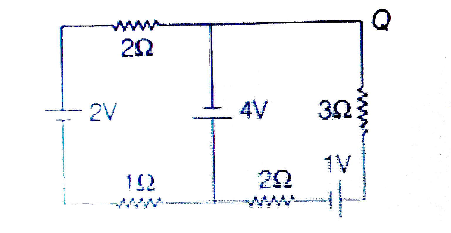
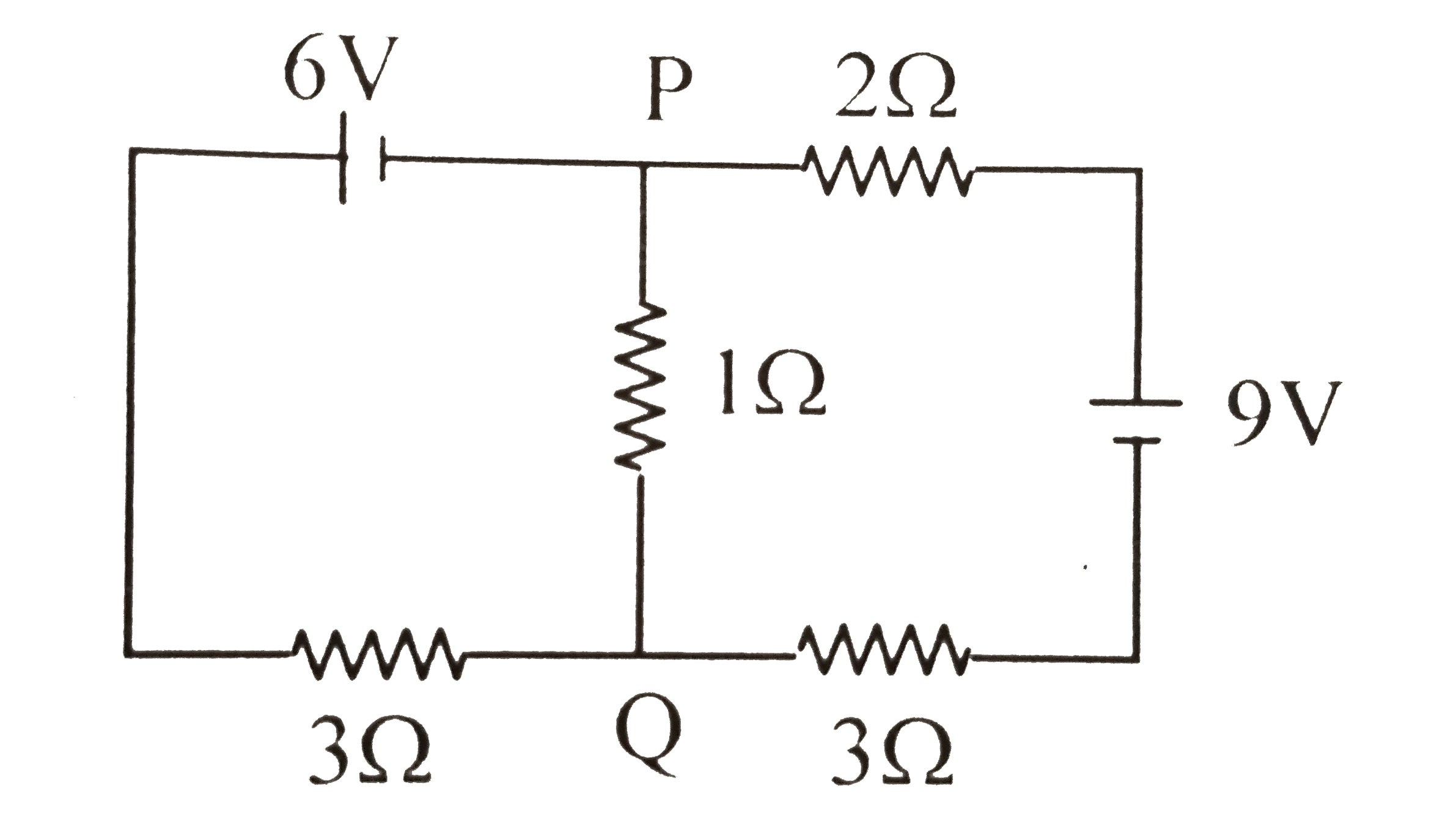
In the circuit shown, what is the potential different VPQ ?
View Solution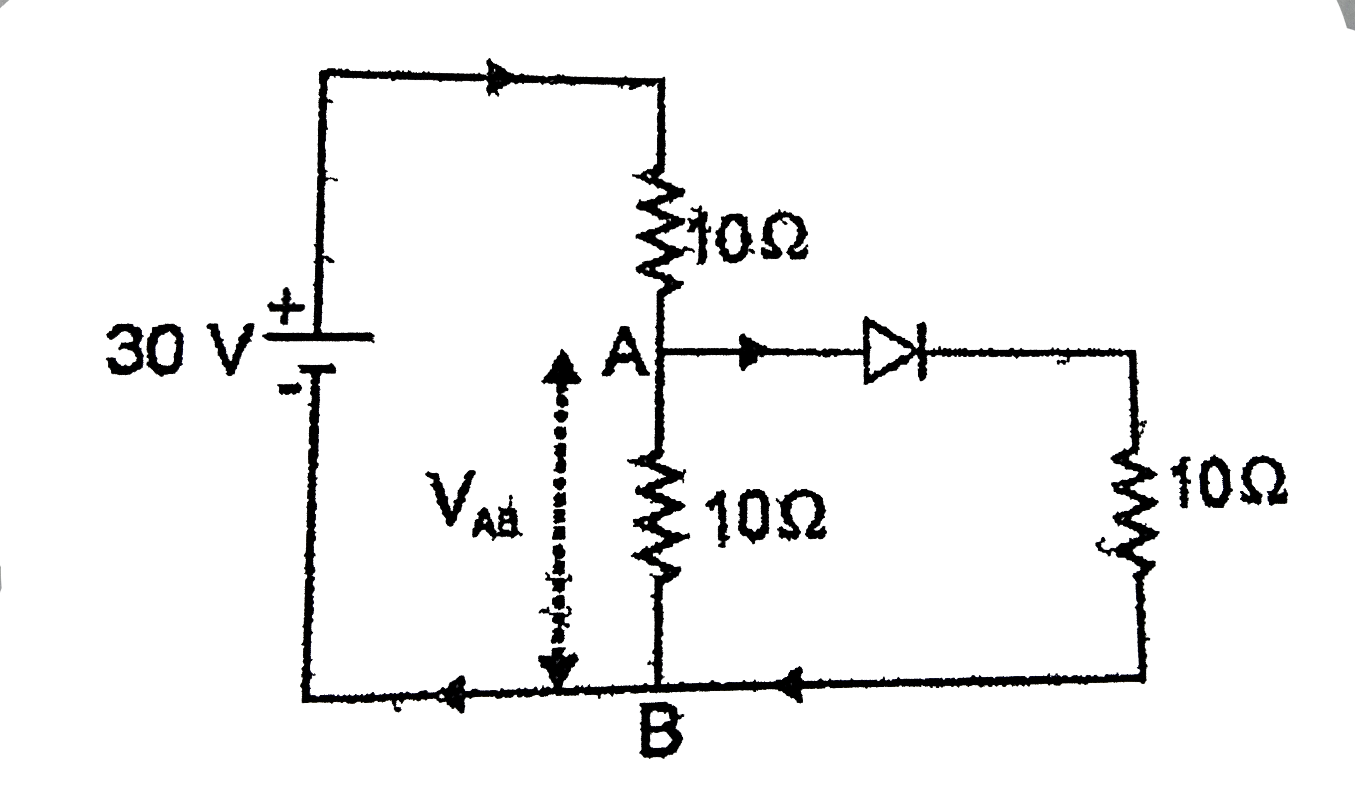
For given circuit potential difference VAB is
View SolutionIn the circuit shown, what is the potential difference VPQ in volts ?

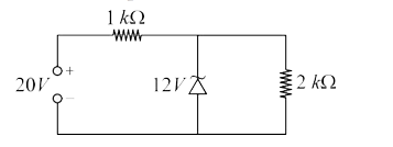
View SolutionIn the given circuit, the current through the resistor 2kΩ is____mA.
View SolutionIn the circuit diagram shown in find the current through the 1Ω resistor.

View SolutionIn the given circuit, calculate -
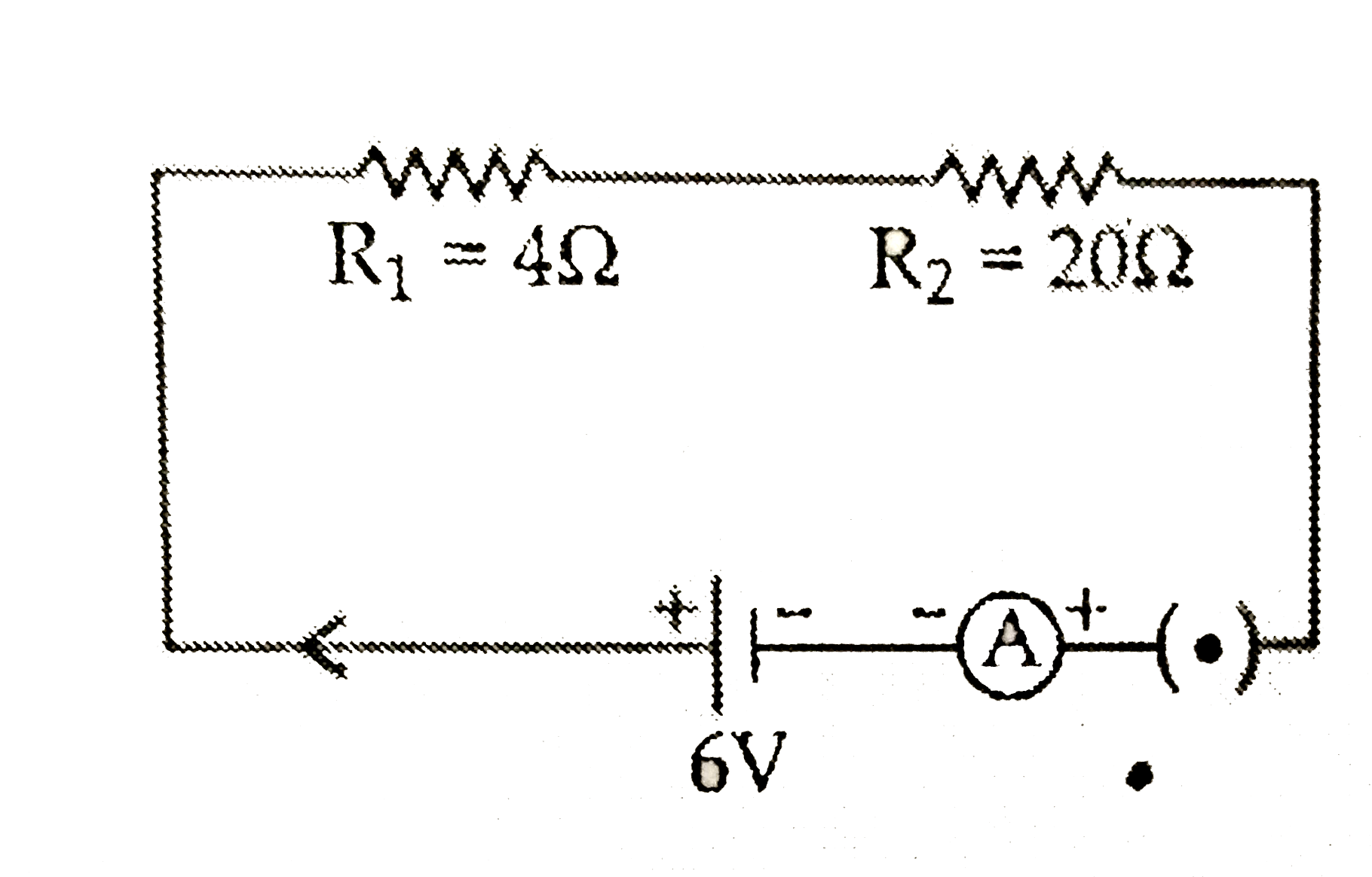
(a) the total resistance of the circuit,
(b) the current through the circuit, and
(c) the potential differences across R1andR2
View SolutionIn the circuit shown, the current in the 1Ω resistor is :
View SolutionIn the part of a circuit shown in figure, the potential different
(VG−VH) between points G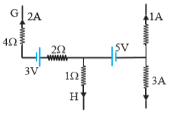
View SolutionIn the circuit shown, calculate the current through 6V battery
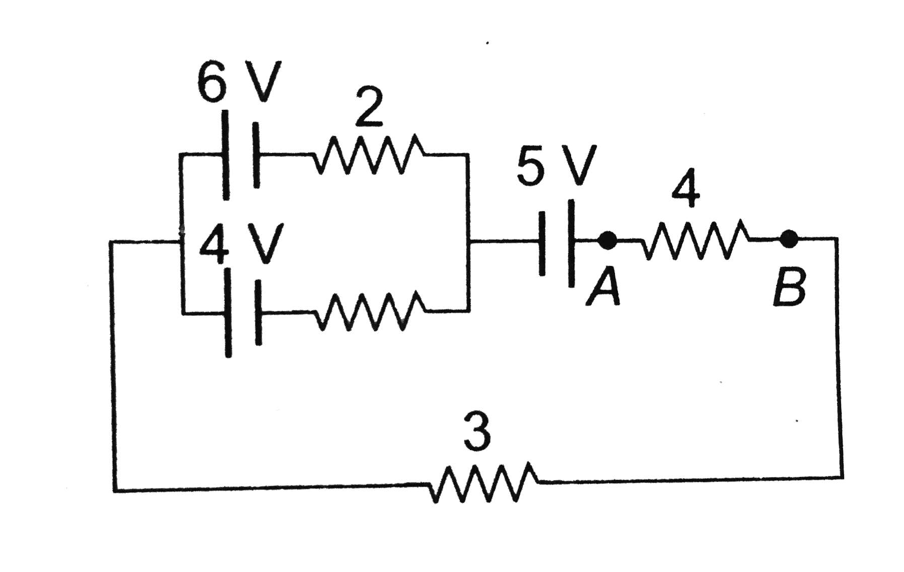
View SolutionFind the current through 4Ω resistor in the circuit shown in figure.
View Solution
