Three identical resistors R1=R2=R3 are connected as shown to a battery of constant e.m.f . The power dissipated is
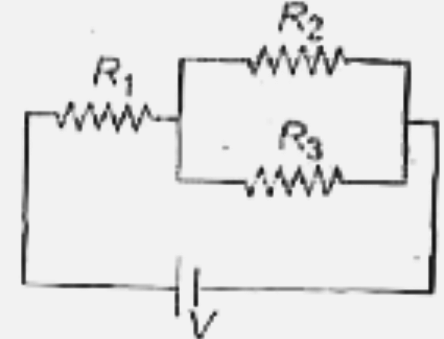
The least in R1
Greatest in R1
In the ratio 1:2 in resistance R1 and R2 respectively
The same in R1 and the parallel combination of R2 and R3
The correct Answer is:B
Step by step video & image solution for Three identical resistors R_(1) = R_(2) = R_(3) are connected as shown to a battery of constant e.m.f . The power dissipated is by Physics experts to help you in doubts & scoring excellent marks in Class 12 exams.
Updated on:21/07/2023Similar Questions
Fig shows three resistor configuration R1,R2andR3 connected to 3V battery. If the power dissipated by the configuration R1,R2andR3 is P1,P2andP3 respectively, then
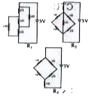
View SolutionFor ensuring dissipation of same energy in all three resistors (R1,R2,R3) connected as shown in figure, their values must be related s

View SolutionTwo resistors R1=400ΩandR2=20Ω are connected in parallel to a battery. If heating power developed in R1 is 25. W. find the heating power developed in R2.
View SolutionFor ensuring dissipation of same energy in all three resistors (R1,R2,R3) connected as shown in figure, their values must be related as

View SolutionFigure shows three resistor configurations R1,R2andR3 connected to 3V battery. If the power dissipated by the configuration R1,R2andR3 is P1,P2andP3, respectively. Then -
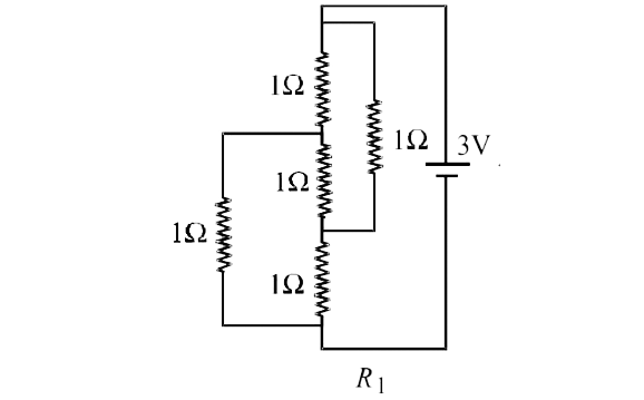
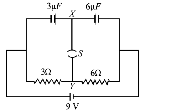
View SolutionThree equal resistors connected in series across a source of emf together dissipate 10W of power. What would be the power dissipated if te same resistors are connected in parallel across the same source of emf?
View Solution(a) Resistors given as R1,R2andR3 are connected in series to a battery V. Draw the circuit diagram showing the arrangement. Derive an expression for the equivalent resistance of the combination.
(b) If R1=10Ω,R2=20ΩandR3=30Ω, calculate the effective resistance when they are connected in series to a battery of 6 V. Also find the current flowing in the circuit.
View SolutionA long solenoid having n = 200 turns per metre has a circular cross-section of radius a1=1cm. A circular conducting loop of radius a2=4cm and resistance R=5(Ω) encircles the solenoid such that the centre of circular loop coincides with the midpoint of the axial line of the solenoid and they have the same axis as shown in Fig.
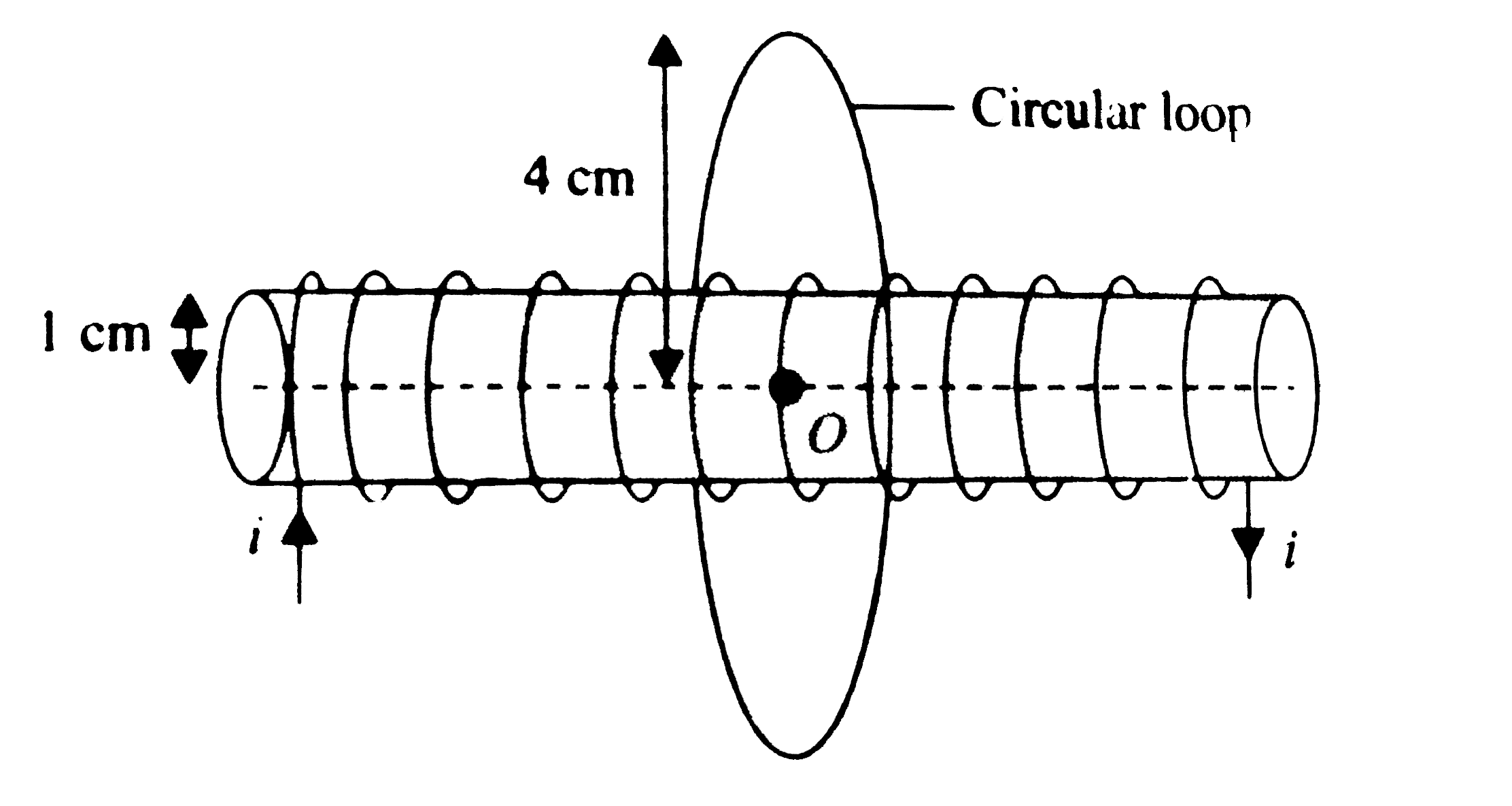
A current 't' in the solenoid results in magnetic field along its axis with magnitude B=(μ)ni at points well inside the solenoid on its axis. We can neglect the insignificant field outside the solenoid. This results in a magnetic flux (ϕ)B through the circular loop. If the current in the winding of solenoid is changed, it will also change the magnetic field B=(μ)0ni and hence also the magnetic flux through the circular loop. Obvisouly, it will result in an induced emf or induced electric field in the circular loop and an induced current will appear in the loop. Let current in the winding of solenoid be reduced at a rate of 75A/sec.
When the current in the solenoid becomes zero so that external magnetic field for the loop stops changing, current in the loop will follow a differenctial equation given by [You may use an approximation that field at all points in the area of loop is the same as at the centre
View SolutionAn inductor of inductance L = 400 mH and resistors of resistance R1=2Ω and R2=2Ω are connected to a battery of emf 12 V as shown in the figure. The internal resistance of the battery is negligible. The switch S is closed at t=0. The potential drop across L as a function of time is
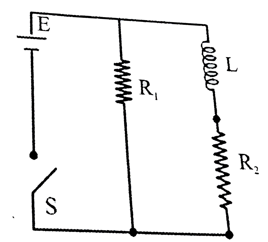
View SolutionAn inductor of inductance L = 400 mH and resistors of resistance R1=2Ω and R2=2Ω are connected to a battery of emf 12 V as shown in the figure. The internal resistance of the battery is negligible. The switch S is closed at t=0. The potential drop across L as a function of time is

View Solution
