Draw a labelled diagram with the necessary switch, regulator, etc. to connect a bulb and a fan with the mains. In what arrangement are they connected to the mains : series or parallel ?
Step-by-Step Text Solution:
1. Understanding the Components: We need to connect a bulb and a fan to the mains supply. Each device requires a switch for independent control.
2. Choosing the Connection Type: The bulb and fan should be connected in a parallel arrangement. This allows each device to operate independently; if one device is turned off, the other can still function.
3. Drawing the Diagram:
- Start with the mains supply, which is typically represented by two lines (live and neutral).
- From the mains supply, draw two separate lines leading to the bulb and fan.
- Connect a switch in series with each device (one switch for the bulb and one for the fan).
- Include a fuse in the circuit to protect against excess current. This can be placed in series with the mains supply.
- If desired, a regulator can be included in the circuit for the fan to control its speed.
4. Labeling the Diagram: Clearly label the components in the diagram:
- Mains Supply
- Bulb
- Fan
- Switch for Bulb
- Switch for Fan
- Fuse
- Regulator (if included)
5. Finalizing the Diagram: Ensure that all connections are clear and that the diagram accurately represents a parallel circuit with the necessary components.
- Start with the mains supply, which is typically represented by two lines (live and neutral).
- From the mains supply, draw two separate lines leading to the bulb and fan.
- Connect a switch in series with each device (one switch for the bulb and one for the fan).
- Include a fuse in the circuit to protect against excess current. This can be placed in series with the mains supply.
- If desired, a regulator can be included in the circuit for the fan to control its speed.
- Mains Supply
- Bulb
- Fan
- Switch for Bulb
- Switch for Fan
- Fuse
- Regulator (if included)
Topper's Solved these Questions
- HOUSEHOLD CIRCUITS BOOK - ICSECHAPTER - HOUSEHOLD CIRCUITS EXERCISE - EXERCISE -9(A) (MULTIPLE CHOICE TYPE)
3 Videos
- HOUSEHOLD CIRCUITS BOOK - ICSECHAPTER - HOUSEHOLD CIRCUITS EXERCISE - EXERCISE -9(B)
58 Videos
- HOUSEHOLD CIRCUITS BOOK - ICSECHAPTER - HOUSEHOLD CIRCUITS EXERCISE - EXERCISE -9(B) (MULTIPLE CHOICE TYPE)
2 Videos
- FORCE BOOK - ICSECHAPTER - FORCE EXERCISE - EXERCISE 1( C) Multiple Choice questions
2 Videos
- MACHINESBOOK - ICSECHAPTER - MACHINESEXERCISE - EXERCISE-3(B) NUMERICALS
11 Videos
Similar Questions
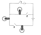
The diagram in Fig. shows three lamps and three switches 1, 2 and 3 connected with two cells.
How are then the lamps connected : in series or in parallel ?

View SolutionThere are two electric bulbs of 40W and 100W. Which one will be brighter when first connected in series and then in parallel ?
View SolutionWhat are the advantages of connecting electrical devices in parallel with the battery instead of connected them in series ?
View SolutionDraw a labelled diagram of an alternating current generator. Write the function of its two main parts.
View SolutionDraw a neat and labelled diagram of a screw gauge. Name its main parts and state their functions.
View SolutionA parallel combination of an 8Ω resistor and an unknown resistor R is connected in series with a 16Ω resistor and a battery. This circuit is then disassembled, and the three resistors are then connected in series with each other oand the same battery. in both arrangements, the current through the 8Ω resistor is the same. What is the unknown resistance R?

View SolutionFig. below shows two bulbs with switches and fuse connected to the mains through a three pin socket by means of a three wires cable.

How are the two bulbs joined : in series or in parallel ?
View SolutionFrom the figures given below, identify the bulbs connected in parallel and in series.

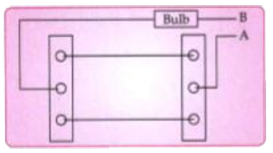
View SolutionThe diagram below shows a dual control switch circuit connected to a bulb.

Out of A and B which one is the live wire and which one is the neutral wire ?
View SolutionDraw a labelled energy band diagram for a solid which is an insulator. What is the main difference between this diagram and that of a semiconductor?
View Solution
