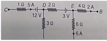
Figure shows a part of a circuit.Find the rate of change as shown.

The correct Answer is:A, B, C, D
Step by step video & image solution for Figure shows a part of a circuit.Find the rate of change as shown. by Physics experts to help you in doubts & scoring excellent marks in Class 12 exams.
Updated on:21/07/2023Topper's Solved these Questions
- ELECTROMAGNETIC INDUCTIONBOOK - RESONANCE ENGLISHCHAPTER - ELECTROMAGNETIC INDUCTIONEXERCISE - Exercis-1 PART 2
51 Videos
- ELECTROMAGNETIC INDUCTIONBOOK - RESONANCE ENGLISHCHAPTER - ELECTROMAGNETIC INDUCTIONEXERCISE - Exercis-2 PART 1
14 Videos
- ELECTROMAGNETIC INDUCTIONBOOK - RESONANCE ENGLISHCHAPTER - ELECTROMAGNETIC INDUCTIONEXERCISE - Problem
12 Videos
- ELECTRODYNAMICSBOOK - RESONANCE ENGLISHCHAPTER - ELECTRODYNAMICSEXERCISE - Advanced level problems
31 Videos
- ELECTROSTATICSBOOK - RESONANCE ENGLISHCHAPTER - ELECTROSTATICSEXERCISE - HLP
40 Videos
Similar Questions
Figure shows a part of the circuit. Which points have the same potential as that of point A:

View SolutionThe following figure shows a part of a circuit,the potential difference between C and B(VC−VB) is

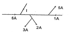
View SolutionIf the figure shows a part of an electric circuit, then the current is

View SolutionFigure shows part of a circuit. If l = 5A and is decreasing at a constant rate of 103A/s then VB−VA is
View SolutionFigure shows part of a circuit. Which points have the same potential as that of point a

View SolutionThe weight of an object on the surface of the Earth is 40 N. Its weight at a height equal to the radius of the Earth is
View SolutionThe network shown in figure is a part of a complete circuit. If at a certain instant, the current i is 4 A and is increasing at a rate of 103A/S. ThenVB−VA will be
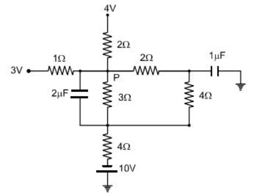
View SolutionThe figure shown is part of the circuit at steady state

The current following from 3Ω resistor is :
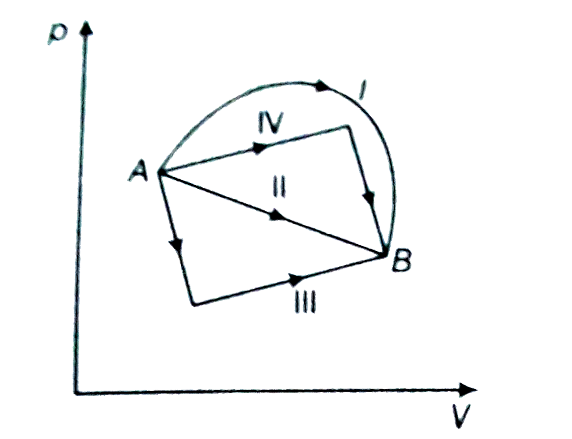
View SolutionFigure shows the p−V diagram of an ideal gas undergoing a change of state from A to B. Four different parts I, II, III and IV as shown in the figure may lead to the same change of state. ltBrgt

View SolutionThe circuit shown in the figure acts as

View Solution
