(i) Find out the charges on the three capacitors connected to a battery as shown in figure. Take C1=1.0μF,C2=2.0μF,C3=3.0μF and V=20 volt
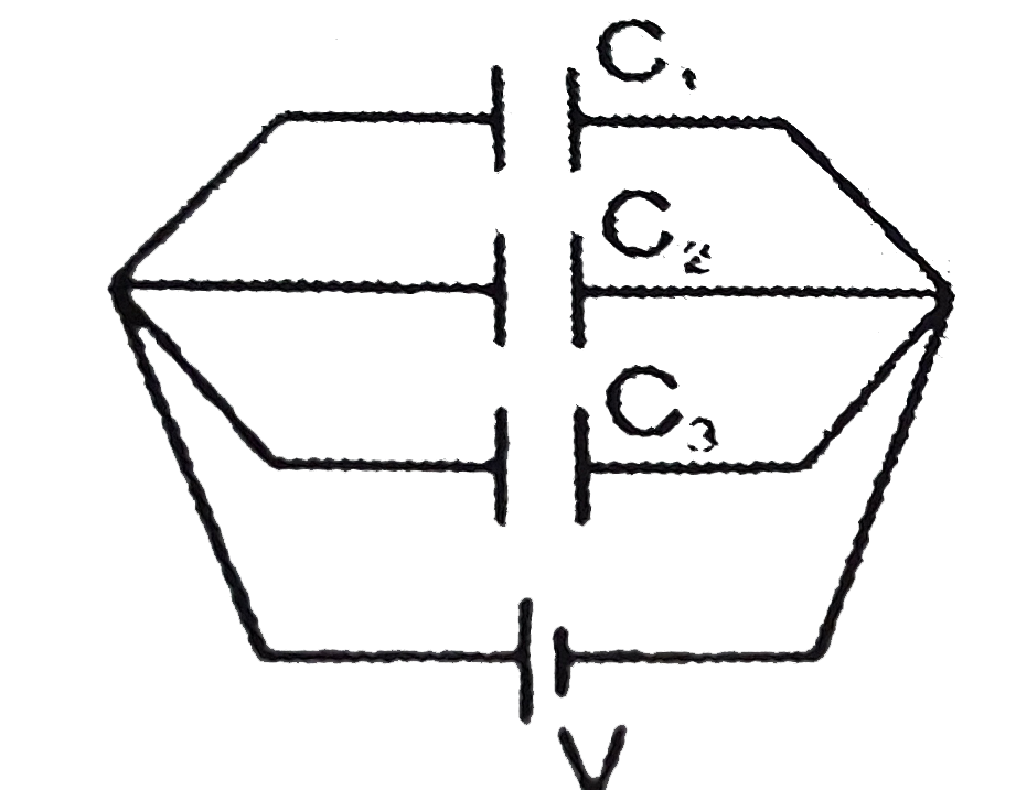
(ii) Find out the work done by the battery during the process of charging (initially all the capacitors are uncharged)
(iii) Find out the total energy stored in the capacitors.
The correct Answer is:(i) 20μC,40μF,60μC
(ii) 2400μJ (iii)1200μJ
Step by step video & image solution for (i) Find out the charges on the three capacitors connected to a battery as shown in figure. Take C_(1)=1.0 mu F , C_(2)=2.0 mu F, C_(3)=3.0 mu F and V=20 volt (ii) Find out the work done by the battery during the process of charging (initially all the capacitors are uncharged) (iii) Find out the total energy stored in the capacitors. by Physics experts to help you in doubts & scoring excellent marks in Class 12 exams.
Updated on:21/07/2023Topper's Solved these Questions
- CAPACITANCEBOOK - RESONANCE ENGLISHCHAPTER - CAPACITANCEEXERCISE - Exercise - 2
74 Videos
- CAPACITANCEBOOK - RESONANCE ENGLISHCHAPTER - CAPACITANCEEXERCISE - Exercise - 3
26 Videos
- CAPACITANCEBOOK - RESONANCE ENGLISHCHAPTER - CAPACITANCEEXERCISE - Miscellaneous Solved Example
3 Videos
- ATOMIC PHYSICSBOOK - RESONANCE ENGLISHCHAPTER - ATOMIC PHYSICSEXERCISE - Advanved level problems
17 Videos
- COMMUNICATION SYSTEMSBOOK - RESONANCE ENGLISHCHAPTER - COMMUNICATION SYSTEMSEXERCISE - Exercise 3
13 Videos
Similar Questions
Find the charges on the three capacitors connected to a bettery as shown in figure (31.E1). Take C_1=2.0,muF, C_2=4.0,muf, C_3=6.0,muF and V=12 volts.
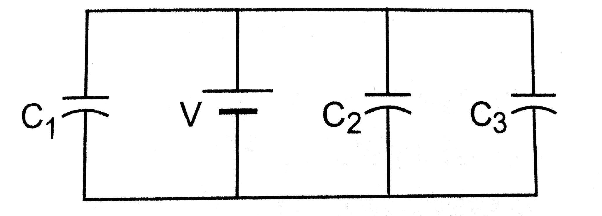
View SolutionFind the charges on the three capacitors connected to a bettery as shown in figure (31.E1). Take C1=2.0=2.0,μF,C2=4.0,μf,C3=6.0,μFandV=12vo<s.(31-E1). Take C1=2.0μF,C2=4.0μF,C2=6.0μFandV=12vo<s.
View Solution
Knowledge Check
An LC circuit contains a 20 mH inductor and 25μF capacitor with an initial charge of 5 mC. The total energy stored in the circuit initially is
A5 JB0.5JC50 JD500 J
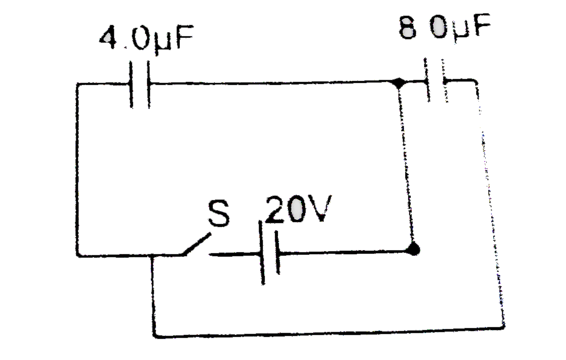
(i) Find the total charge flown through the battery in the arrangement shown in figure after switch S is closed (initially all the capacitors are uncharged).
(ii) Find out final charge on each capacitor.
View Solution
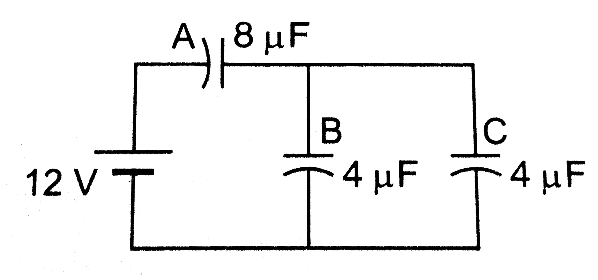
(i) Find the equivalent capacitance of the combination shown in the figure (a), when C1=2.0μF,C2=4.0μFandC3=3.0μF
(ii) The input terminals A and B in Fig. (a) are connected to a battery of 12 V. Find the potential and the charge of each capacitor.
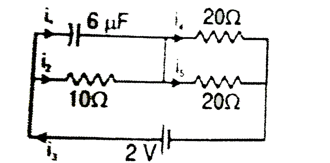
View SolutionIn steady state, find the charge on the capacitor in (μC) shown in figure.
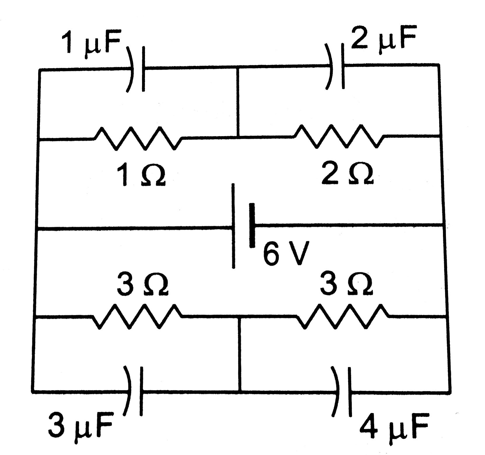
View SolutionFind the charge on the four capacirtors of capacitances 1(mu)F,2(mu)F,3(mu)F,and 4(mu)F, shown in figure.
View SolutionA capacitor of capacitance 6 μF is connected with an emf sourface 3 V. Electrostaci energy stored in the capacitor is
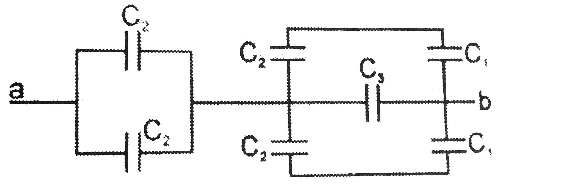
View SolutionA combination arrangement of the capacitors is shown in the figure
(i) C1=3μF,C2=6μF and C3=2μF then equivalent capacitance between 'a' and 'b' is :
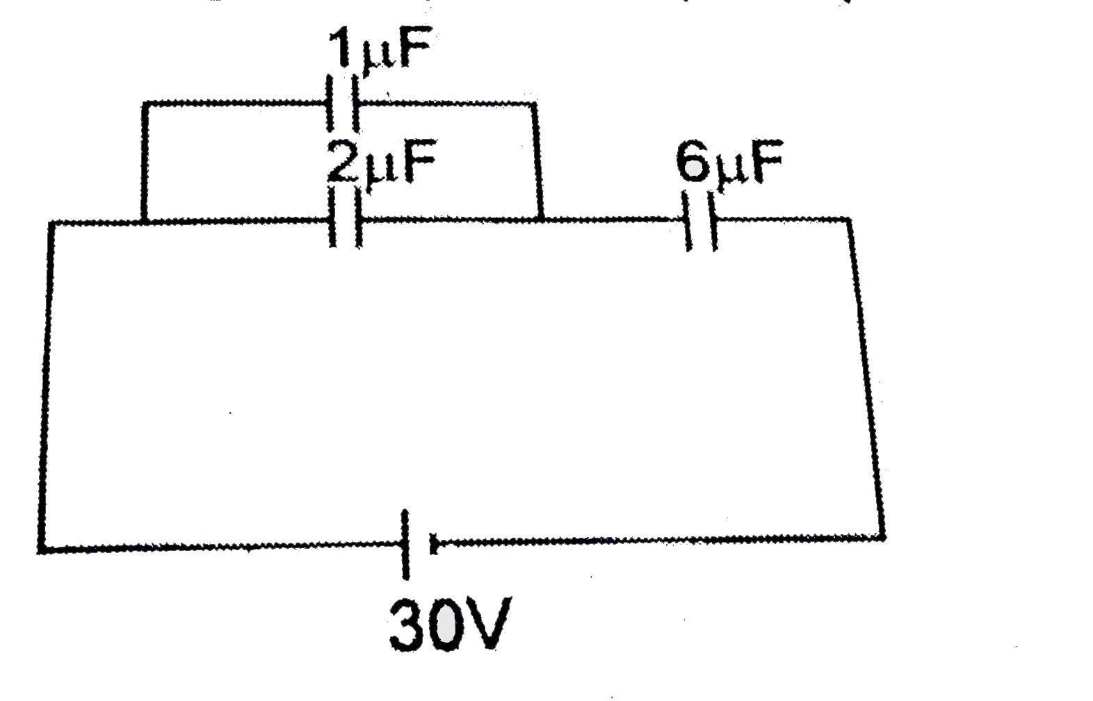
View SolutionIn the given circuit find out charge on 6μF and 1μF capacitor.
View Solution
