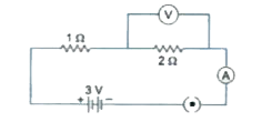
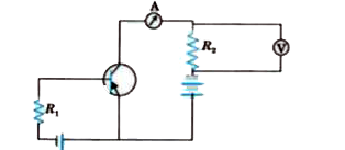
Distinguish between ammeter and voltmeter.
Step by step video & image solution for Distinguish between ammeter and voltmeter. by Physics experts to help you in doubts & scoring excellent marks in Class 12 exams.
Updated on:21/07/2023Topper's Solved these Questions
- QUESTION BANK 2021Book:NAVNEET PUBLICATION - MAHARASHTRA BOARDChapter:QUESTION BANK 2021Exercise:CURRENT ELECTRICITY ( Short Answer II (SA2) ( 3 MARKS Each ) )
Explore 7 Videos
- QUESTION BANK 2021Book:NAVNEET PUBLICATION - MAHARASHTRA BOARDChapter:QUESTION BANK 2021Exercise:CURRENT ELECTRICITY (Long Answer ( LA) ( 4 marks Each) )
Explore 2 Videos
- QUESTION BANK 2021Book:NAVNEET PUBLICATION - MAHARASHTRA BOARDChapter:QUESTION BANK 2021Exercise:CURRENT ELECTRICITY (Very Short Answer (VSA) ( 1 MARK Each ) )
Explore 10 Videos
- MULTIPLE CHOICE QUESTIONSBook:NAVNEET PUBLICATION - MAHARASHTRA BOARDChapter:MULTIPLE CHOICE QUESTIONSExercise:Communication Systems
Explore 6 Videos
- SHORT ANSWER QUESTIONSBook:NAVNEET PUBLICATION - MAHARASHTRA BOARDChapter:SHORT ANSWER QUESTIONSExercise:Assignments
Explore 3 Videos
Similar Questions
Knowledge Check
In the circuit shown here, the readings of the ammeter and voltmeter are
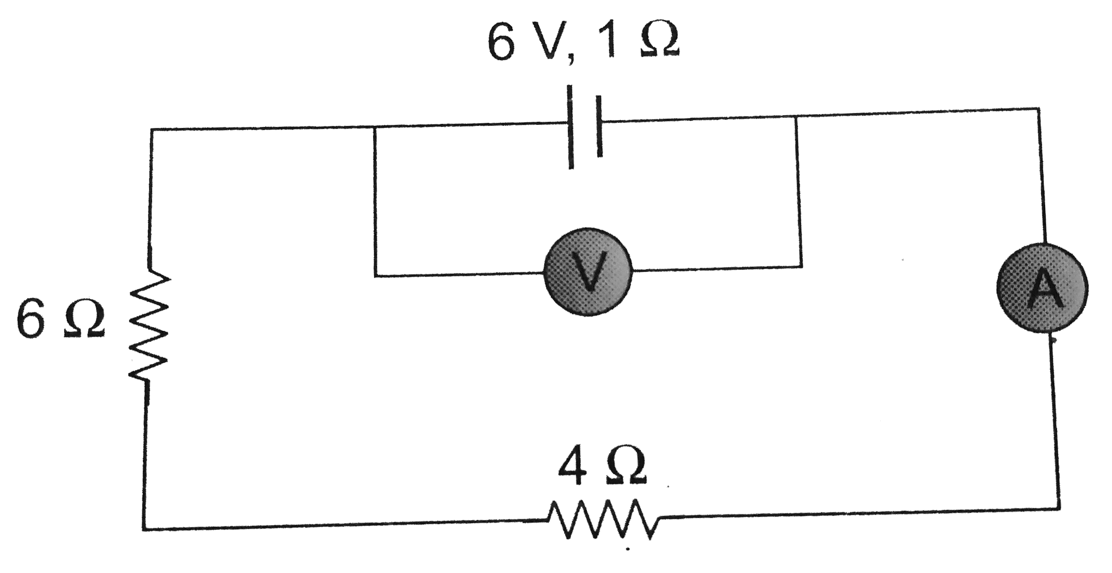 A6A,60VB0.6A,6VC6/11A,60/11VD11/6A,11/60V
Find the readings of the ammeter (A) and voltmeter (V):
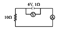 A6 A, 60 VB0.6A, 6VC6A, 6VD611A,6011V
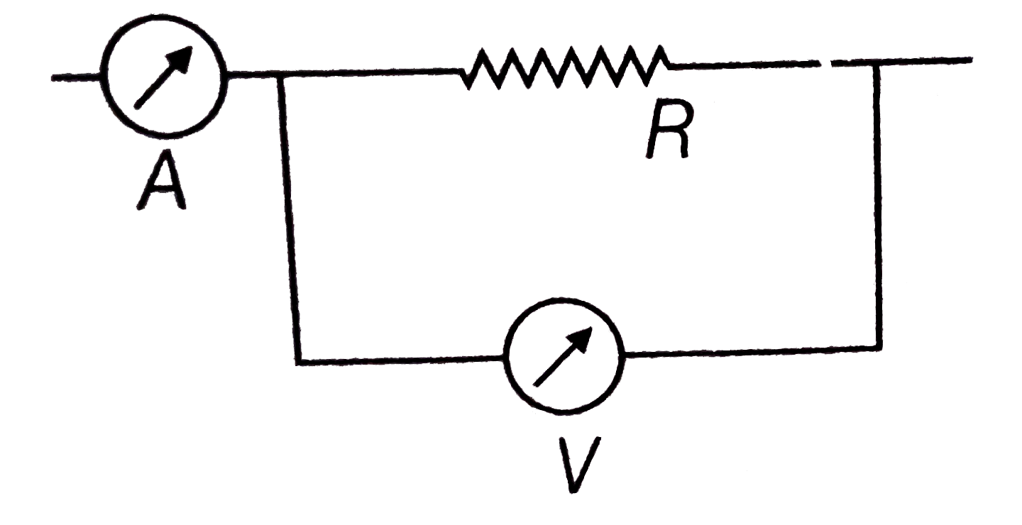
Assertion : In the circuit shown in figure ammeter and voltmeter are non-ideal. Why positions of ammeter and voltmeter are changed, reading of ammeter will increase while of voltmeter will decrease.
Reason : Resistance of an ideal ammeter is zero while that of an ideal voltmeter is infinite.AIf both Assertion and Reason are true and the Reason is correct explanation of the Assertion.BIf both Assertion and Reason are true but Reason is not the correct explanation of Assertion.CIf Assertion is true, but the Reason is false.DIf Assertion is false but the Reason is true.
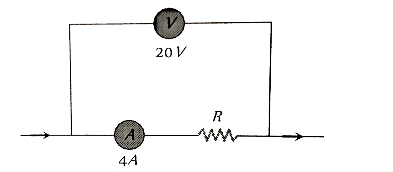
In the diagram shown, the reading of voltmeter is 20 V and that of ammeter is 4 A . The value of R should be (Consider given ammeter and voltmeter are not ideal)
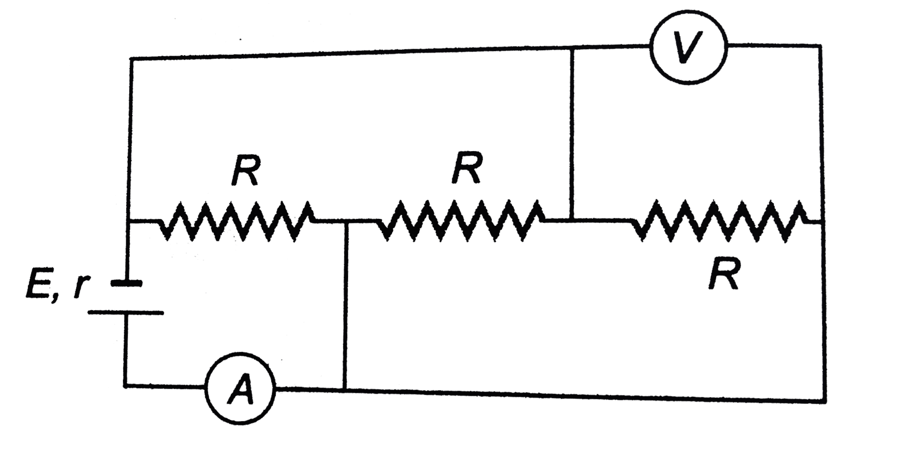
View SolutionIn the circuit shown in figure ammeter and voltmeter are ideal. If E=4V,R=9Ω and r=1Ω then readings of ammeter and voltmeter are
View SolutionA students connects an ammeter A and a voltmeter V to measure a resistancer as shown in figure. If the voltmeter reads 20V and the ammeter reads 4A, then R is

View SolutionFor the adjoining circuit diagram, the readings of ammeter and voltmeter are 2A and 120 V respectively. If the value of R is 75Ω, then the voltmeter resistance will be
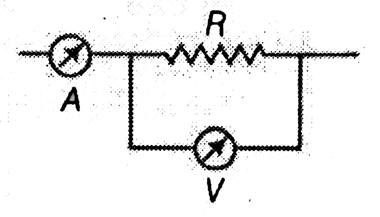
View SolutionIn the adjoining circuit diagram, the readings of ammeter and voltmeter are 2 A and 120 V, respectively. If the value of R is 75Ω, then the voltmeter resistance will be
View Solution

