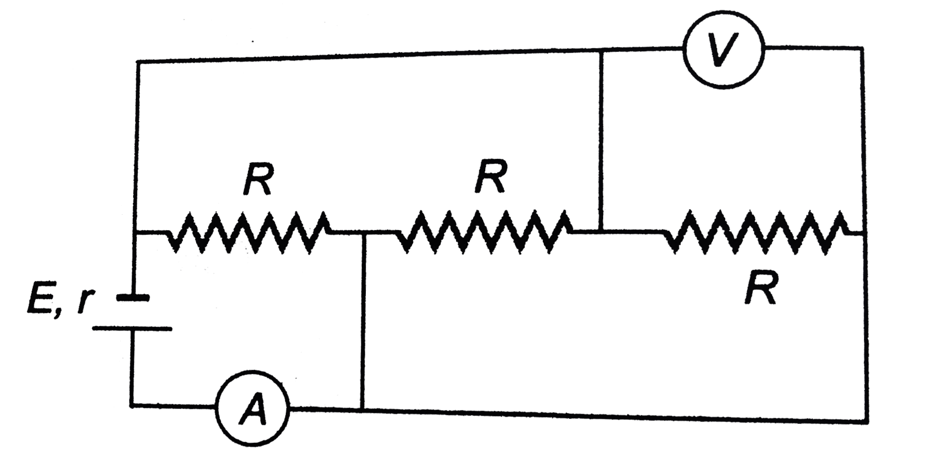
In the circuit shown in figure ammeter and voltmeter are ideal. If E=4V,R=9Ω and r=1Ω then readings of ammeter and voltmeter are
1A,3V
2A,3V
3A,4V
4A,4V
The correct Answer is:A
All these resistors are in paralllel.
∴Rnet=R3+r=4Ω
Hence, the main current
i=ERnet=1A
Current through either of the resistance
isi3=or13A
∴V=iR=(13)(9)=3V
Topper's Solved these Questions
- CURRENT ELECTRICITYBook:DC PANDEYChapter:CURRENT ELECTRICITYExercise:Level 2 More Than One Correct
Explore 10 Videos
- CURRENT ELECTRICITYBook:DC PANDEYChapter:CURRENT ELECTRICITYExercise:Level 2 Comprehension Example Type
Explore 2 Videos
- CURRENT ELECTRICITYBook:DC PANDEYChapter:CURRENT ELECTRICITYExercise:Level 1 Subjective
Explore 53 Videos
- COMMUNICATION SYSTEMBook:DC PANDEYChapter:COMMUNICATION SYSTEMExercise:Subjective
Explore 11 Videos
- ELECTROMAGNETIC INDUCTIONBook:DC PANDEYChapter:ELECTROMAGNETIC INDUCTIONExercise:Medical entrances gallery
Explore 25 Videos
Similar Questions
Knowledge Check
In the circuit shwon in figure, ammeter and voltmeter are ideal. E=4V,R=15Ω and r=1Ω, then reading of ammter (in A) and voltmeter (in V) respectively are:
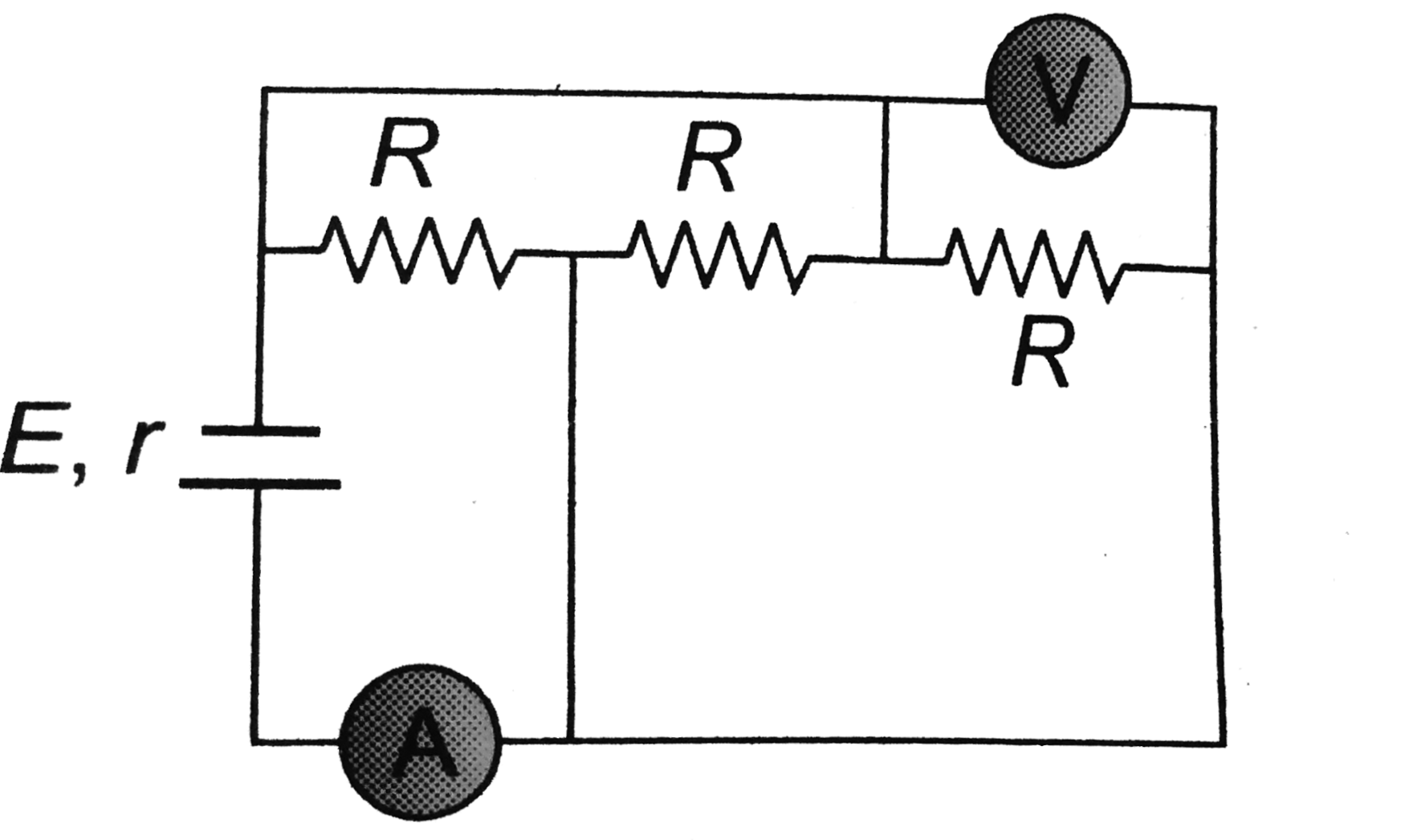 A2/3,11/3B2/3,10/3C10/3,2/3Dnone of these
In the circuit shown here, the readings of the ammeter and voltmeter are
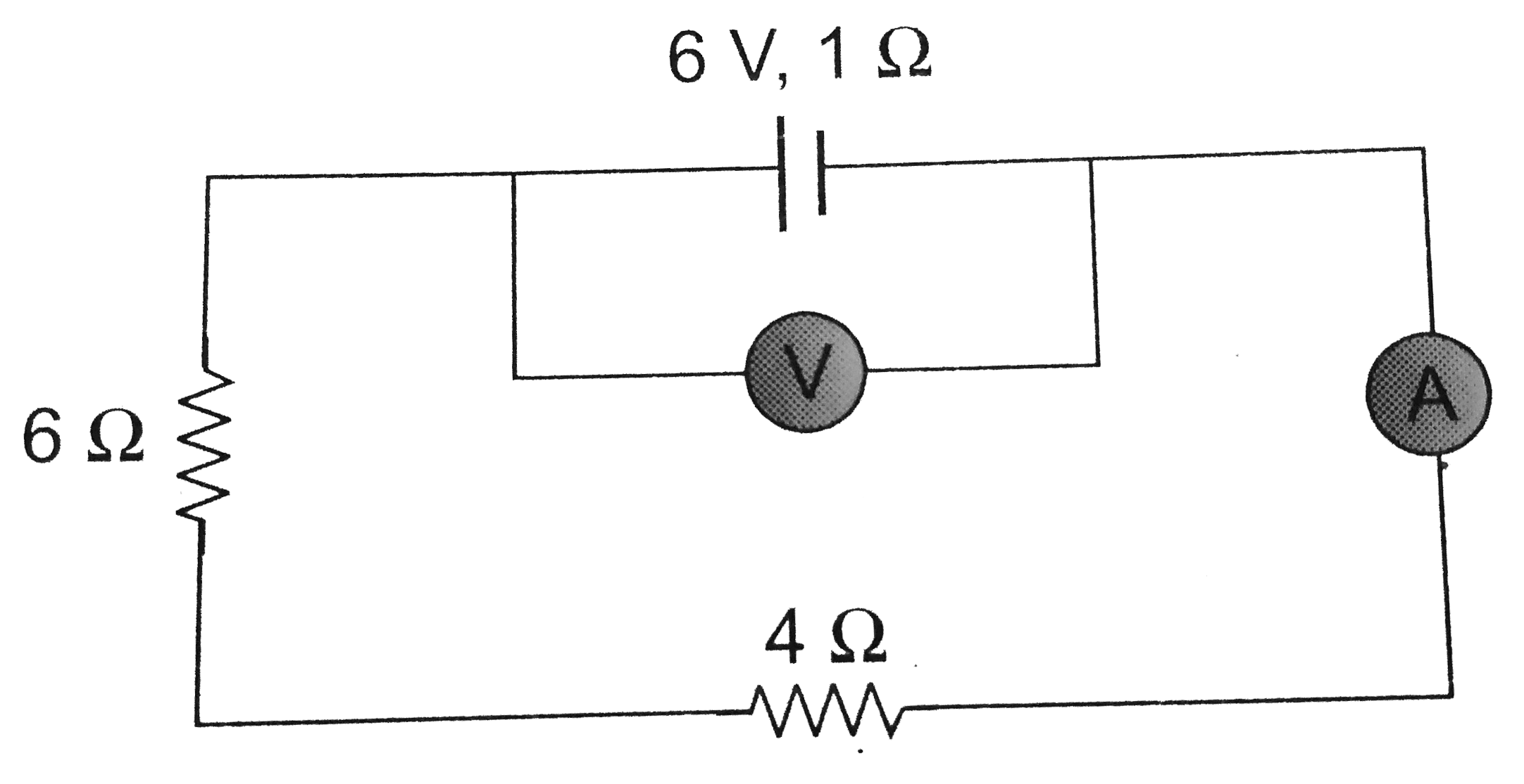 A6A,60VB0.6A,6VC6/11A,60/11VD11/6A,11/60V
Find the readings of the ammeter (A) and voltmeter (V):
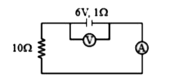 A6 A, 60 VB0.6A, 6VC6A, 6VD611A,6011V
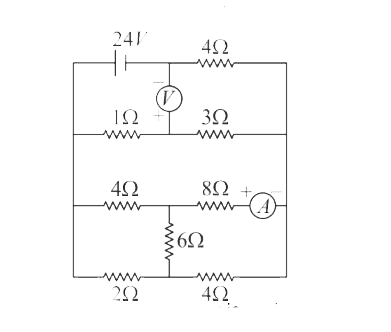
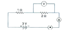
In the circuit shown in figure,an ideal ammeter and an ideal voltmeter are used.When the key is open,the voltmeter reads "1.53V".When the key is ,the ammeter reads "1.0A" and the voltmeter reads "1.03V" .The resistance "R" is
View Solution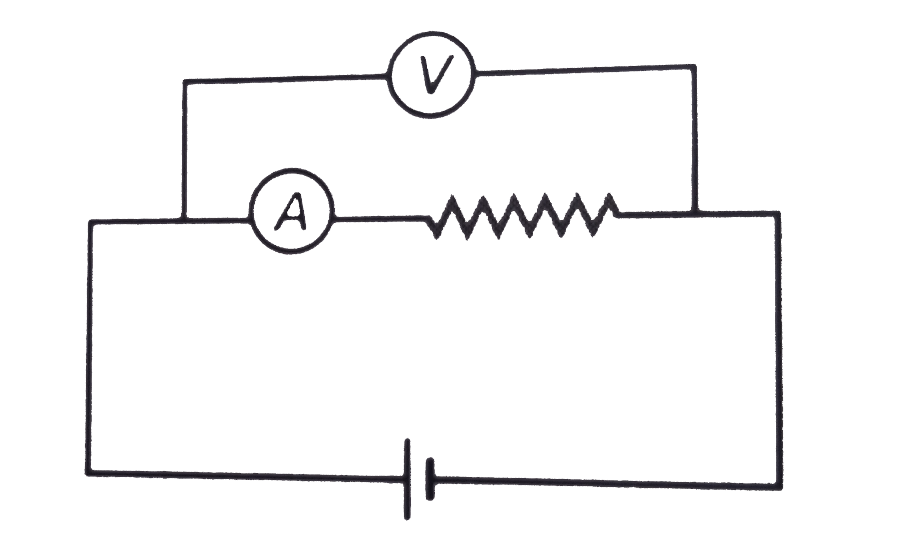
Assertion : In the circuit shown in figure ammeter and voltmeter are non-ideal. Why positions of ammeter and voltmeter are changed, reading of ammeter will increase while of voltmeter will decrease.
Reason : Resistance of an ideal ammeter is zero while that of an ideal voltmeter is infinite.
View Solution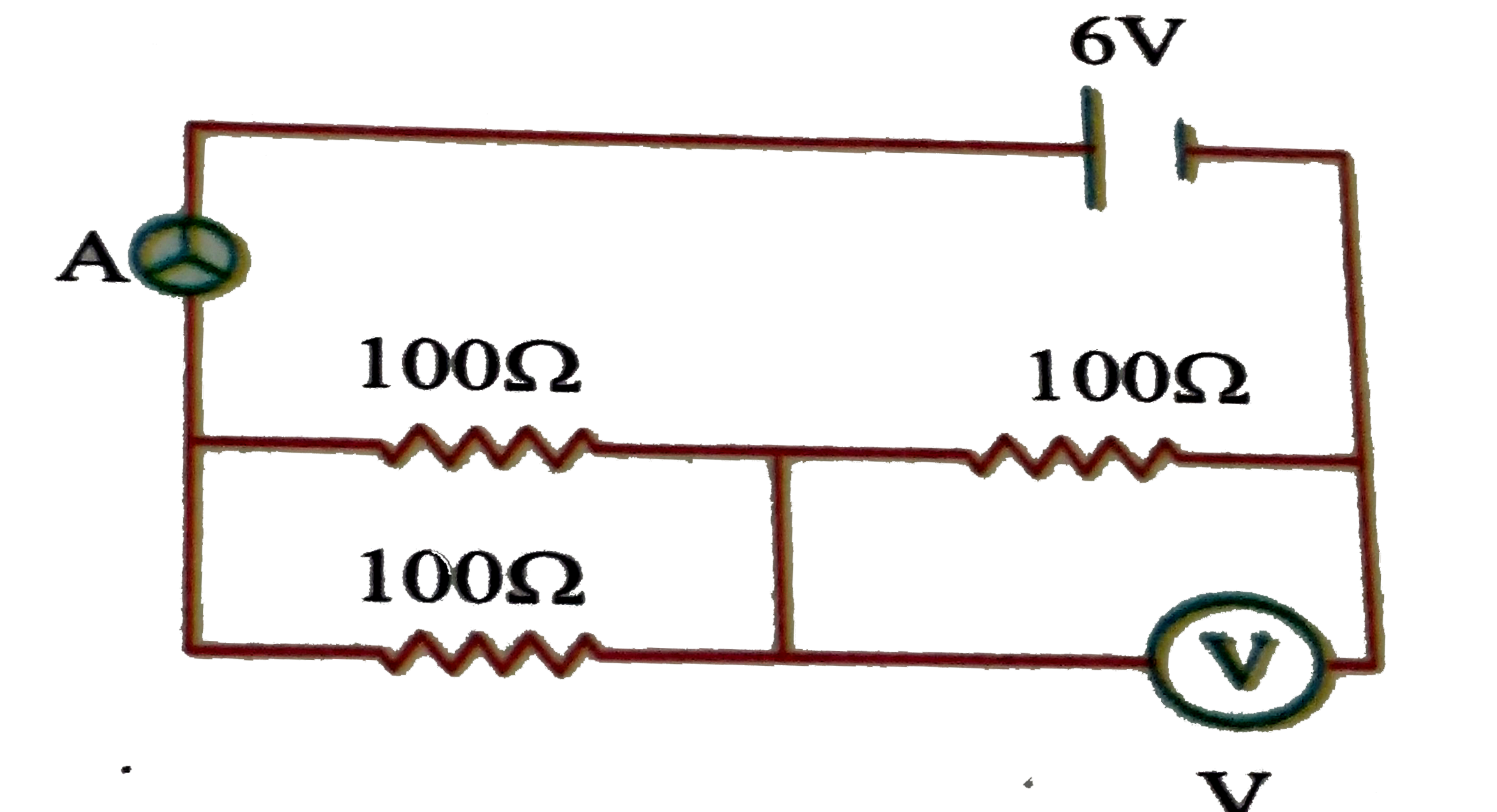
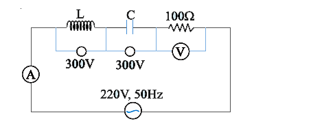
In the circuit shown, the reading of the voltmeter and the ammeter are
View SolutionIn the circuit shown in figure, what will be the readings of voltmeter and ammeter?
View SolutionIn the circuit shown, A and V are ideal ammeter and voltmeter respectively. Reading of the voltmeter will be
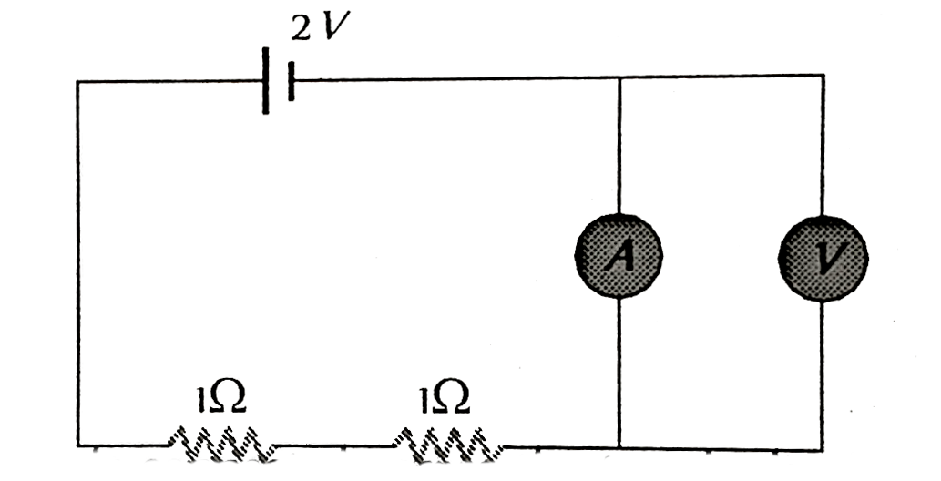
View Solution
