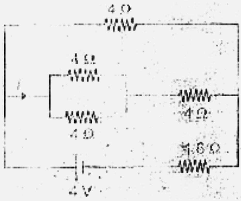
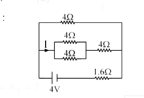
In the circuit shown the value of I in ampere is :
A
1
B
C
0.4
D
1.5
Video Solution
Text Solution
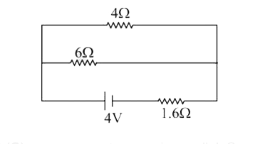
Use current dividing rules
|
Topper's Solved these Questions
- DC CIRCUITBook:VMC MODULES ENGLISHChapter:DC CIRCUITExercise:LEVEL-1 DAILY TUTORIAL SHEET-3
Explore 15 Videos
- DC CIRCUITBook:VMC MODULES ENGLISHChapter:DC CIRCUITExercise:LEVEL-1 DAILY TUTORIAL SHEET-4
Explore 15 Videos
- DC CIRCUITBook:VMC MODULES ENGLISHChapter:DC CIRCUITExercise:LEVEL-1 DAILY TUTORIAL SHEET-1
Explore 15 Videos
- CURRENT ELECTRICITYBook:VMC MODULES ENGLISHChapter:CURRENT ELECTRICITYExercise:IN-CHAPTER EXERCISE-F
Explore 10 Videos
- DYNAMICS OF A PARTICLEBook:VMC MODULES ENGLISHChapter:DYNAMICS OF A PARTICLEExercise:JEE Advance (Archive) Level - II (SINGLE OPTION CORRECT TYPE )
Explore 31 Videos
Similar Questions
Knowledge Check
In the circuit shown, the value of currents I1,I2andI3 are
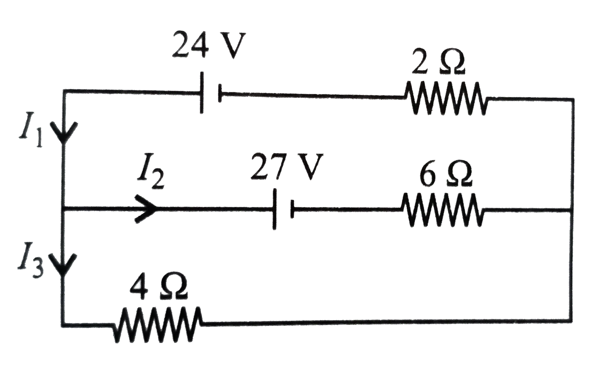 A3A,−3A2A,92AB92A,−32AC5A,4A,−3AD7A,54A,92A
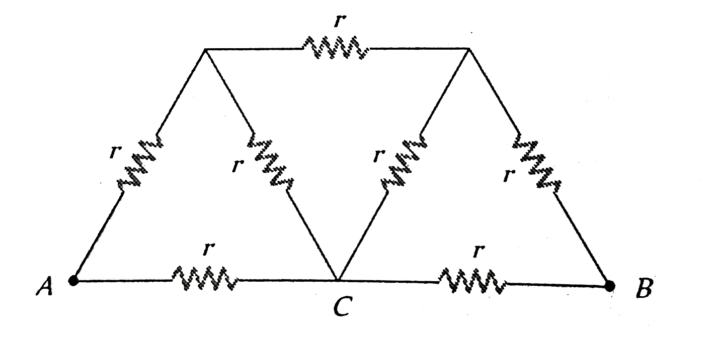
In the circuit shown, the value of each resistance is r , then equivalent resistance of circuit between points A and B will be
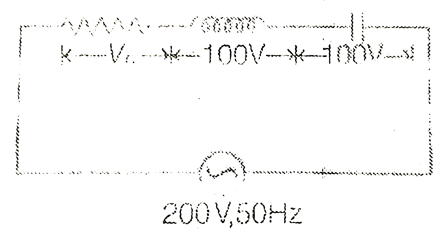
View SolutionIn the circuit shown in figure value of VR is
View SolutionIn the circuit shown in fig., the value of I1+I2 is
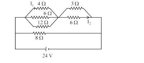
View SolutionIn the circuit shown in fig., the value of I1+I2 is

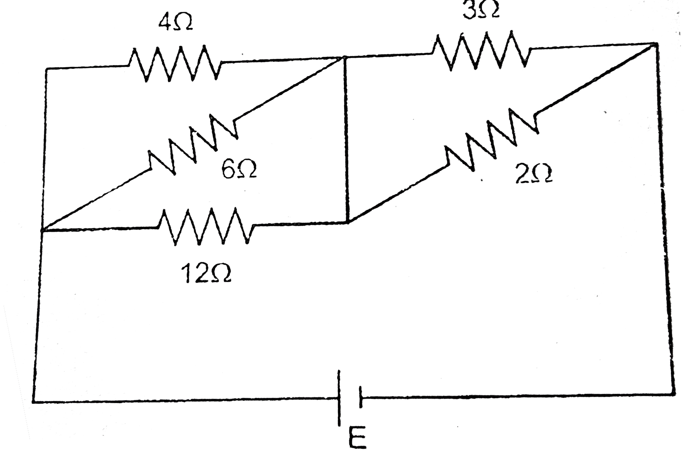
View SolutionIn the shown circuit
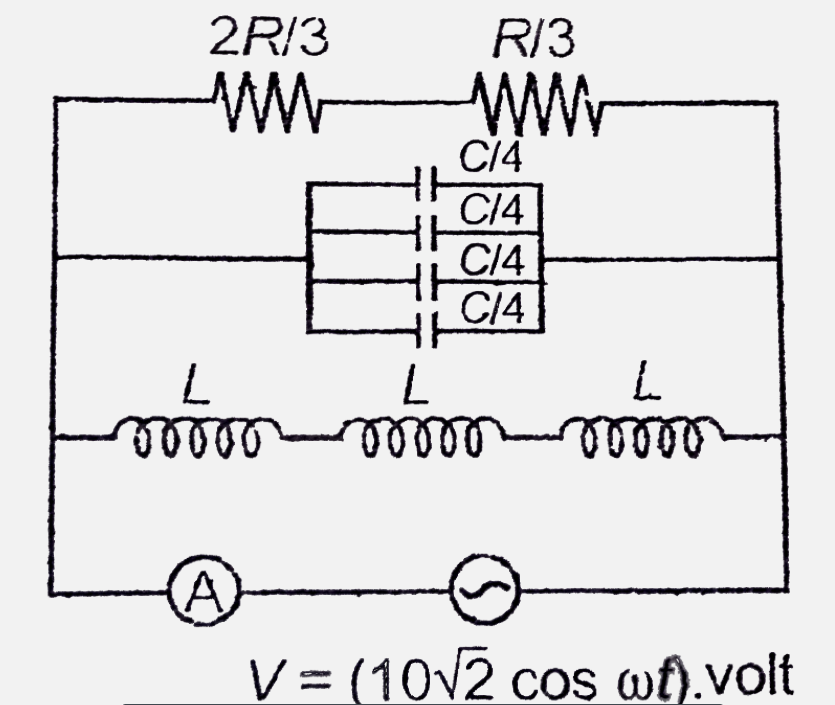
View SolutionIn the circuit shown, reactance of each capacitor is 4R, and that of each inductor is R3 . If R=5Ω then find reading of ammeter (in amperes)
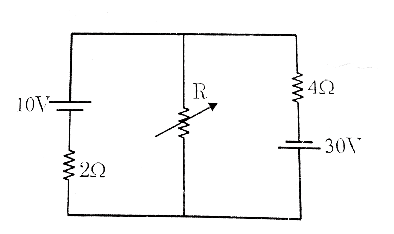
View SolutionIn the circuit shown in the figure, the value of maximum rate of heat production in resistance R is
View Solution

