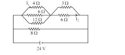
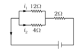
In the circuit shown, the currents I1 and I2 are if the applied potential is of 12V,internal resistance 1 ohm:
(A) i1=3A,i2=1A
(B) i1=1A,i2=3A
(C)i1=0.6A,i2=1.8.A
(D)i2=1.5A,i1=0.5A
Step by step video & image solution for In the circuit shown, the currents I_1 and I_2 are if the applied potential is of 12V,internal resistance 1 ohm: by Physics experts to help you in doubts & scoring excellent marks in Class 12 exams.
Updated on:21/07/2023Topper's Solved these Questions
- DC CIRCUITBOOK - VMC MODULES ENGLISHCHAPTER - DC CIRCUITEXERCISE - LEVEL-1 DAILY TUTORIAL SHEET-3
15 Videos
- DC CIRCUITBOOK - VMC MODULES ENGLISHCHAPTER - DC CIRCUITEXERCISE - LEVEL-1 DAILY TUTORIAL SHEET-4
15 Videos
- DC CIRCUITBOOK - VMC MODULES ENGLISHCHAPTER - DC CIRCUITEXERCISE - LEVEL-1 DAILY TUTORIAL SHEET-1
15 Videos
- CURRENT ELECTRICITYBOOK - VMC MODULES ENGLISHCHAPTER - CURRENT ELECTRICITYEXERCISE - IN-CHAPTER EXERCISE-F
10 Videos
- DYNAMICS OF A PARTICLEBOOK - VMC MODULES ENGLISHCHAPTER - DYNAMICS OF A PARTICLEEXERCISE - JEE Advance (Archive) Level - II (SINGLE OPTION CORRECT TYPE )
31 Videos
Similar Questions
Knowledge Check
In the circuit shown, the value of currents I1,I2andI3 are
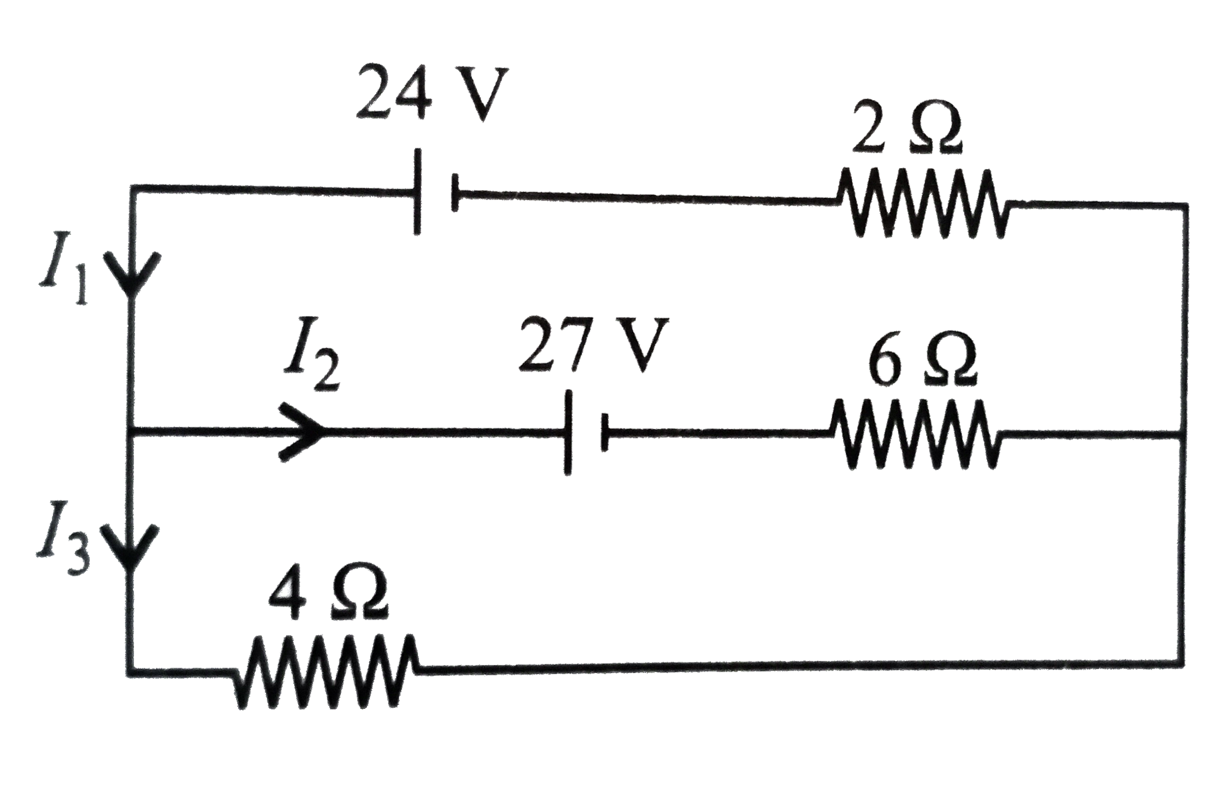 A3A,−3A2A,92AB92A,−32AC5A,4A,−3AD7A,54A,92A
In the circuit as shown in figure, the ratio of current i1/i2 is
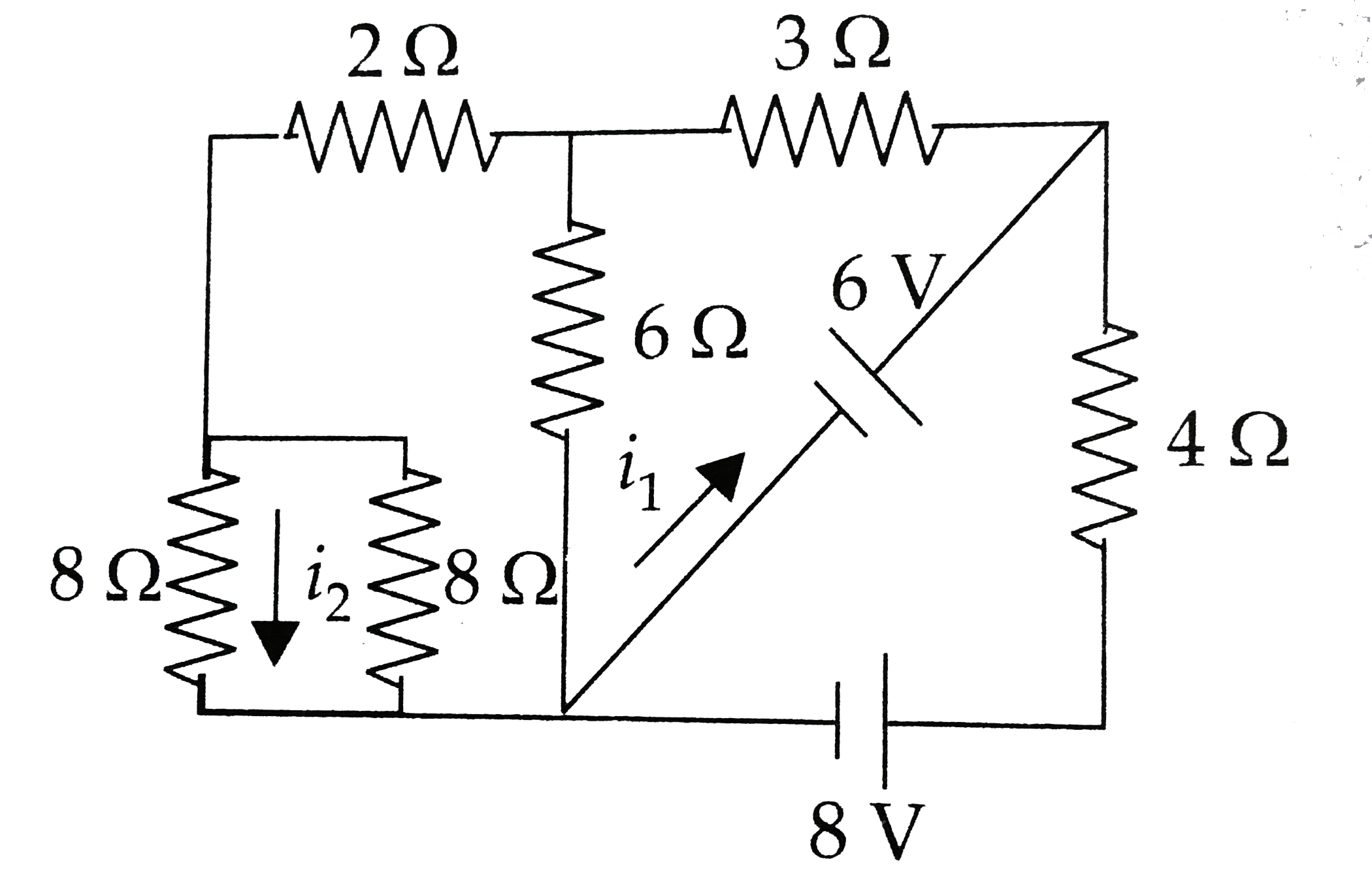
View SolutionIn the circuit shown, the switch is closed at t=0, the currents I1,I2 and I3 are
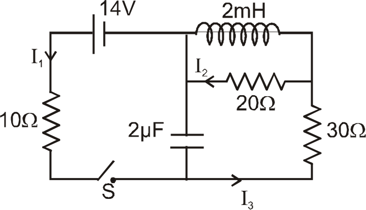
View SolutionIn the circuit shown i1i2 will be equal to
_PHY_E05_301_Q01.png)
View SolutionIn the circuit shown E,F,G and H are cells of emf 2V,1V,3V and 1V respectively and their internal resistance are 2Ω,1Ω,3Ω and 1Ω respectively.
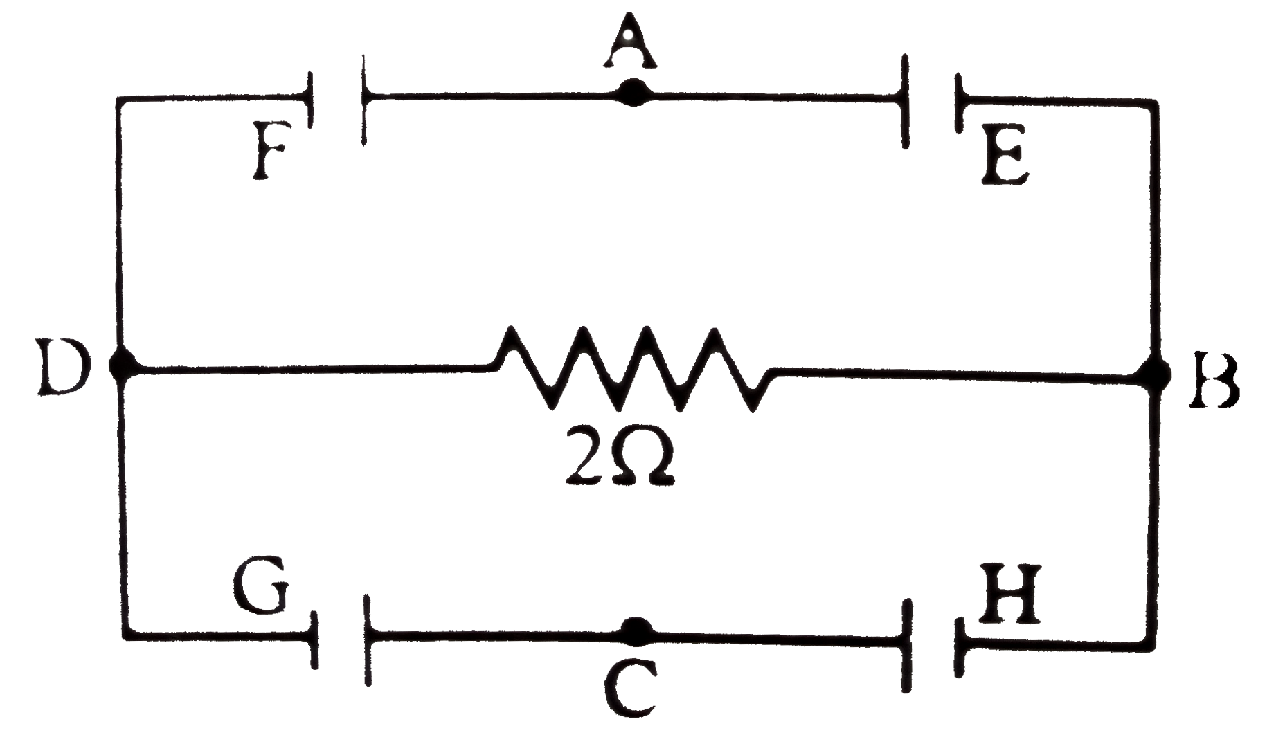
View SolutionIn the circuit shown E,F,G and H are cells of emf 2V,1V,3V and 1V respectively and their internal resistance are 2Ω,1Ω,3Ω and 1Ω respectively.

View SolutionIn the circuit shown in the figure The steady state currents i1andi2 in the coils after the switch S is closed are
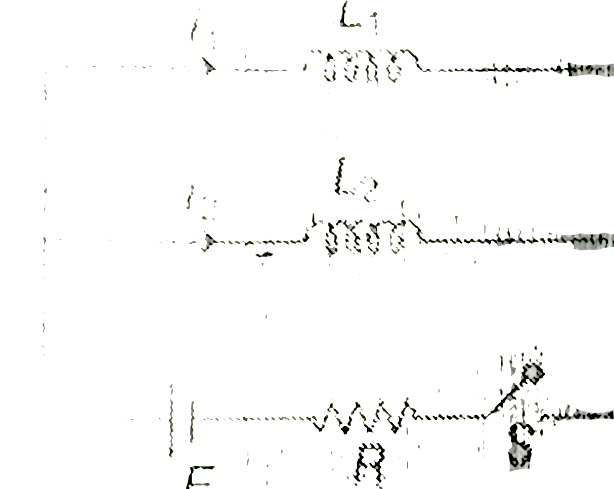
View SolutionIn the circuit as shown, it is given that R1/R2=1/2 and potential at O is V. The resistance R2 is-
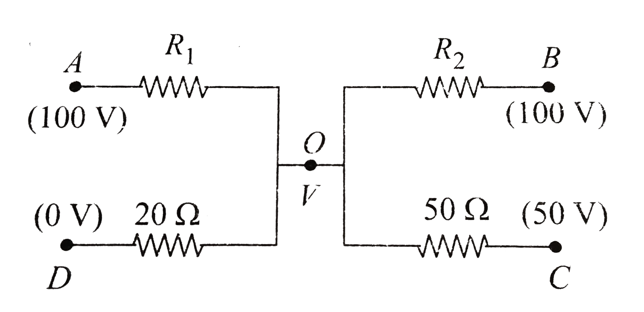
View Solution

