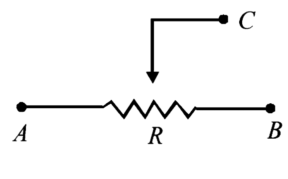
We can use a rheostat as a potential divider.
To solve the question of how a rheostat can be used as a potential divider, we can break it down into several steps:
1. Understanding the Rheostat:
- A rheostat is a variable resistor used to control current in a circuit. It has three terminals: two fixed terminals and one sliding contact (wiper) that can move along a resistive element.
2. Setting Up the Circuit:
- Consider a circuit with a voltage source (V) connected across a rheostat. Let’s denote the voltage source as 30V. The two fixed terminals of the rheostat will be connected to points A and B, while the sliding terminal (C) can be adjusted along the resistive element.
3. Calculating Current (I):
- The total resistance of the rheostat between points A and B is denoted as R_AB. The current (I) flowing through the circuit can be calculated using Ohm's Law:
I=VRAB
- Here, V is the total voltage across the rheostat.
4. Voltage Across the Sliding Contact (V_BC):
- The voltage across the sliding contact (from point C to point B) can be expressed as:
VBC=I×RBC
- Where R_BC is the resistance between points B and C.
5. Relating Current and Voltage:
- Substituting the expression for I from step 3 into the equation for V_BC gives:
VBC=(VRAB)×RBC
6. Effect of Sliding the Contact:
- When the sliding contact (C) is moved towards A, the length of the resistive path (R_BC) increases, which increases the resistance and thus increases the voltage V_BC.
- Conversely, if the sliding contact (C) is moved towards B, the length of the resistive path decreases, which decreases the resistance and thus decreases the voltage V_BC.
7. Conclusion:
- By adjusting the position of the sliding contact on the rheostat, we can vary the resistance and consequently the voltage across the output terminals (V_BC). This allows the rheostat to function as a potential divider, enabling us to obtain a desired voltage output from a higher voltage source.
- A rheostat is a variable resistor used to control current in a circuit. It has three terminals: two fixed terminals and one sliding contact (wiper) that can move along a resistive element.
- Consider a circuit with a voltage source (V) connected across a rheostat. Let’s denote the voltage source as 30V. The two fixed terminals of the rheostat will be connected to points A and B, while the sliding terminal (C) can be adjusted along the resistive element.
- The total resistance of the rheostat between points A and B is denoted as R_AB. The current (I) flowing through the circuit can be calculated using Ohm's Law:
I=VRAB
- Here, V is the total voltage across the rheostat.
- The voltage across the sliding contact (from point C to point B) can be expressed as:
VBC=I×RBC
- Where R_BC is the resistance between points B and C.
- Substituting the expression for I from step 3 into the equation for V_BC gives:
VBC=(VRAB)×RBC
- When the sliding contact (C) is moved towards A, the length of the resistive path (R_BC) increases, which increases the resistance and thus increases the voltage V_BC.
- Conversely, if the sliding contact (C) is moved towards B, the length of the resistive path decreases, which decreases the resistance and thus decreases the voltage V_BC.
- By adjusting the position of the sliding contact on the rheostat, we can vary the resistance and consequently the voltage across the output terminals (V_BC). This allows the rheostat to function as a potential divider, enabling us to obtain a desired voltage output from a higher voltage source.
Topper's Solved these Questions
- DC CIRCUITBOOK - VMC MODULES ENGLISHCHAPTER - DC CIRCUITEXERCISE - LEVEL-1 JEE MAIN ARCHIVE
93 Videos
- CURRENT ELECTRICITYBOOK - VMC MODULES ENGLISHCHAPTER - CURRENT ELECTRICITYEXERCISE - IN-CHAPTER EXERCISE-F
10 Videos
- DYNAMICS OF A PARTICLEBOOK - VMC MODULES ENGLISHCHAPTER - DYNAMICS OF A PARTICLEEXERCISE - JEE Advance (Archive) Level - II (SINGLE OPTION CORRECT TYPE )
31 Videos
Similar Questions
Schematic of a rheostat is shown in the figure. Connect a battery to it so that the rheostat acts as a potential divider.Specify which are the input and output terminals

View SolutionHow a battery is to be connected so that the shown rheostat will behave like a potential divider? Also indicate the points about which output can be taken.
 .
.
View SolutionAre we free to call the potential of earth (+ 100 V) instead of zero ? What effect would such an assumption have on measured values of
A potentials
B potential difference ?
View SolutionA cell having an emf E and internal resistance r is connected across a variable external resistance R. As the resistance R is increased, the plot of potential difference V across R is given by
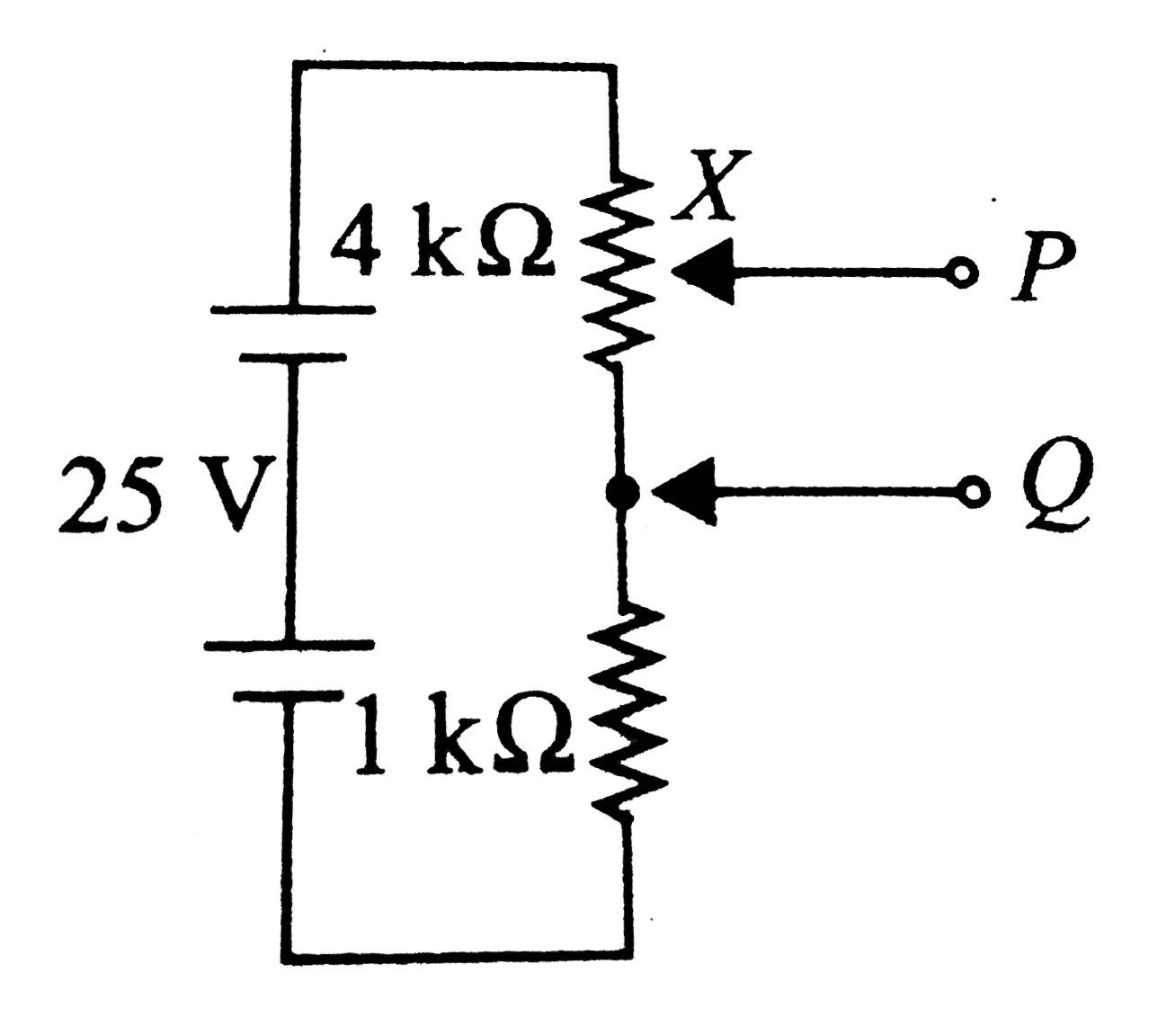
View SolutionShows a potential divider circuit, which, by adjusctment of the position of the contact X, can be used to provide a variable potential difference betweenn the terminals P and Q. what are the limits of this potential difference?

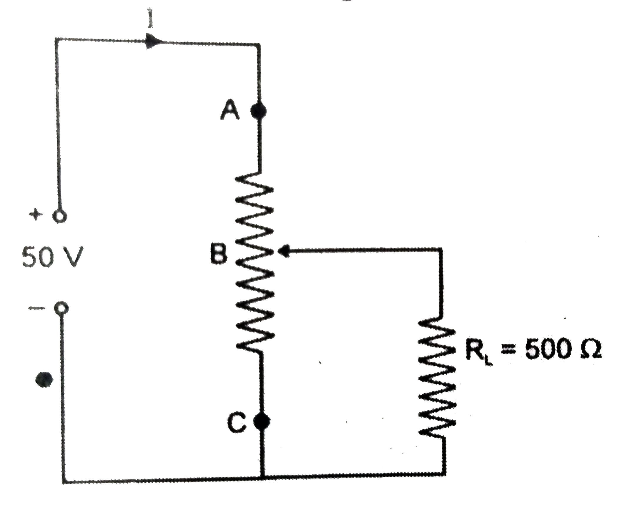
View SolutionAs shown in figure a variable rheostat of 2kΩ is used to control the potential difference across 500 ohm load. (i) If the resistance AB is 500Ω, what is the potential difference across the load ? (ii) If the load is removed, what should be the resistance at BC to get 40 volt btween B and C ?

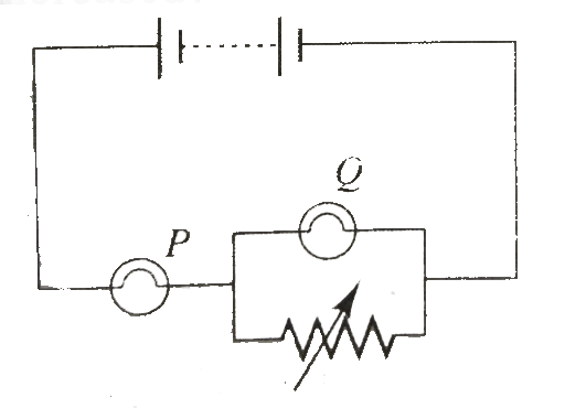
View SolutionThe circuit shownin Fig. 7.33 contains a battery , a rheostat , and two identical lamps. What will happen to the brightness of the lamps if the resistance of the rheostat is increased?

View SolutionThe circuit shownin Fig. 7.33 contains a battery , a rheostat , and two identical lamps. What will happen to the brightness of the lamps if the resistance of the rheostat is increased?

View SolutionIn case of a moving body as force of friction is μmg, can we regard μmgx as potential energy similar to mgh?
View SolutionIn a certain region of space, the electric field is zero. From this, we can conclude that the electric potential in this region is:
View Solution