Draw the circuit for experimental verification of Ohm's law using a source of variable DC voltage, a main resistance of 100Ω, two galvanometers and two resistances of value 106Ω and 10−3Ω respectively. Clearly show the positions of the voltmeter and the ammeter.
Step by step video & image solution for Draw the circuit for experimental verification of Ohm's law using a source of variable DC voltage, a main resistance of 100 Omega, two galvanometers and two resistances of value 10^6 Omega and 10^-3Omega respectively. Clearly show the positions of the voltmeter and the ammeter. by Physics experts to help you in doubts & scoring excellent marks in Class 12 exams.
Updated on:21/07/2023Topper's Solved these Questions
- DC CIRCUITBOOK - VMC MODULES ENGLISHCHAPTER - DC CIRCUITEXERCISE - LEVEL-1 JEE MAIN ARCHIVE
93 Videos
- CURRENT ELECTRICITYBOOK - VMC MODULES ENGLISHCHAPTER - CURRENT ELECTRICITYEXERCISE - IN-CHAPTER EXERCISE-F
10 Videos
- DYNAMICS OF A PARTICLEBOOK - VMC MODULES ENGLISHCHAPTER - DYNAMICS OF A PARTICLEEXERCISE - JEE Advance (Archive) Level - II (SINGLE OPTION CORRECT TYPE )
31 Videos
Similar Questions
Draw the circuit for experimental verfication of Ohm's law using a source of variable DC voltage, a main resistance of 100(Ω), two galvanometers and two resistances of values 106Ω and 10−3 respectively. Clearly show the positions of the voltmeter and the ammeter.
View Solutiontwo galvanometers of resistance 100Ωand50Ω, are 10−8A/div and 2×10⁻⁵A/div respectively. In which case the voltage sensitivity is more ?
View Solution
Knowledge Check
A galvanometer of resistance 70Ω, is converted to an ammeter by a shunt resistance r3=0.03Ω. The value of its resistance will become
A0.025ΩB0.022ΩC0.035ΩD0.030Ω
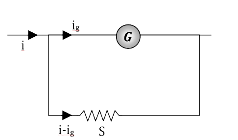
A galvanometer vaving 50 divisions provided with a variable shunt S is used to measure the current when conneted in series with a resistance of 90Ω and a battery of internal resistance 10Ω. It is observed that when the snt resistaces are 10Ω&70Ω respectively, the deflection are respectively 9 and 30 dividions. What is the resistance of the galvanometer ? Further, if the full scale deflection of the galvanometer movement require 200 mA. find the emf of the cell.
View SolutionTo send 10% of the main current through a moving coil galvanometer of resistance 9 Ω, shunt S required is

View SolutionTwo batteries with emf 12 V and 13V are connected in parallel across a load resistor of 10Ω . The internal resistances of the two batteries are 1Ωand2Ω respectively . The voltage across the load lies between
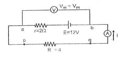
View SolutionThe figure shows a source (a battery) with an emf E of 12 V with an internal resistance r of 2Ω and an external resistance of 4Ω is added to complete the circuit. What are the voltmeter and ammeter readings

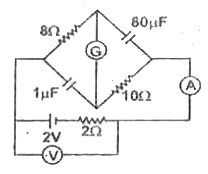
View SolutionThe ammeter (A) and voltmeter (V) in the given circuit are ideal but the galvanometer has a resistance of 2Ω In steady state

View SolutionA galvanometer having 50 divisions provided with a variable shunt S is used to measure the current when connected in series with a resistance of 90Ω and a battery of internal resistance 10Ω. It is observed that when the shunt resistances are 10Oemga and 50Ω, the deflections are, respectively, 9 and 30 divisions. What is the resistance of the galvanometer
View SolutionA cell of emf 3.4V and internal resistance 3Ω is connected to an ammeter having resistance 2Ω and to an external resistance of 100Ω. When a voltmeter is connected across the 100Ω resistance, the ammeter reading is 0.04A. Find the voltage reading by the voltmeter and its resistance. Had the voltmeter been an ideal one what would have been its reading?
View Solution
