The power factor of LCR circuit at resonance is-
0.707
1
Zero
0.5
The correct Answer is:B
To determine the power factor of an LCR circuit at resonance, we can follow these steps:
1. Understanding Power Factor:
The power factor (PF) is defined as the cosine of the phase angle (φ) between the voltage and the current in an AC circuit. Mathematically, it is expressed as:
Power Factor=cosϕ=RZ
where R is the resistance and Z is the impedance of the circuit.
2. Expression for Impedance (Z):
The impedance Z of an LCR circuit is given by:
Z=√R2+(XL−XC)2
where XL is the inductive reactance and XC is the capacitive reactance.
3. Condition at Resonance:
At resonance in an LCR circuit, the inductive reactance XL equals the capacitive reactance XC:
XL=XC
This means that the difference (XL−XC) becomes zero.
4. Simplifying Impedance at Resonance:
Substituting XL=XC into the impedance formula, we get:
Z=√R2+02=√R2=R
5. Calculating Power Factor at Resonance:
Now, substituting Z=R back into the power factor equation:
Power Factor=cosϕ=RZ=RR=1
6. Conclusion:
Therefore, the power factor of an LCR circuit at resonance is:
Power Factor=1
Final Answer:
The power factor of an LCR circuit at resonance is 1.
---
The power factor (PF) is defined as the cosine of the phase angle (φ) between the voltage and the current in an AC circuit. Mathematically, it is expressed as:
Power Factor=cosϕ=RZ
where R is the resistance and Z is the impedance of the circuit.
The impedance Z of an LCR circuit is given by:
Z=√R2+(XL−XC)2
where XL is the inductive reactance and XC is the capacitive reactance.
At resonance in an LCR circuit, the inductive reactance XL equals the capacitive reactance XC:
XL=XC
This means that the difference (XL−XC) becomes zero.
Substituting XL=XC into the impedance formula, we get:
Z=√R2+02=√R2=R
Now, substituting Z=R back into the power factor equation:
Power Factor=cosϕ=RZ=RR=1
Therefore, the power factor of an LCR circuit at resonance is:
Power Factor=1
The power factor of an LCR circuit at resonance is 1.
Topper's Solved these Questions
- ELECTROMAGNETIC INDUCTION & ALTERNATIVE CURRENT Book:VMC MODULES ENGLISHChapter:ELECTROMAGNETIC INDUCTION & ALTERNATIVE CURRENT Exercise:EFFICIENT
Explore 49 Videos
- ELECTROMAGNETIC INDUCTION & ALTERNATIVE CURRENT Book:VMC MODULES ENGLISHChapter:ELECTROMAGNETIC INDUCTION & ALTERNATIVE CURRENT Exercise:IMPECCABLE
Explore 52 Videos
- ELECTROMAGNETIC INDUCTION & ALTERNATIVE CURRENT Book:VMC MODULES ENGLISHChapter:ELECTROMAGNETIC INDUCTION & ALTERNATIVE CURRENT Exercise:IMPECCABLE
Explore 52 Videos
- ELECTROMAGNETIC INDUCTION & ALTERNATING CURRENTBook:VMC MODULES ENGLISHChapter:ELECTROMAGNETIC INDUCTION & ALTERNATING CURRENTExercise:IN-CHAPTER EXERCISE-G
Explore 10 Videos
- ELECTROSTATICSBook:VMC MODULES ENGLISHChapter:ELECTROSTATICSExercise:JEE Advanced (Archive)
Explore 89 Videos
Similar Questions
Knowledge Check
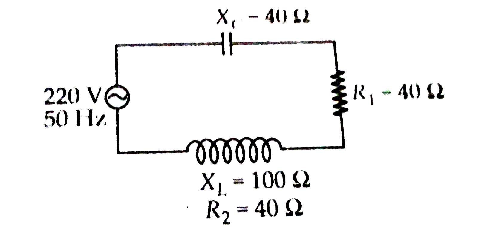
The power factor of the circuit as shown in figure is
 A0.2B0.4C0.8D0.6
The power factor of a series LCR circuit is
View SolutionIn series LCR circuit at resonance
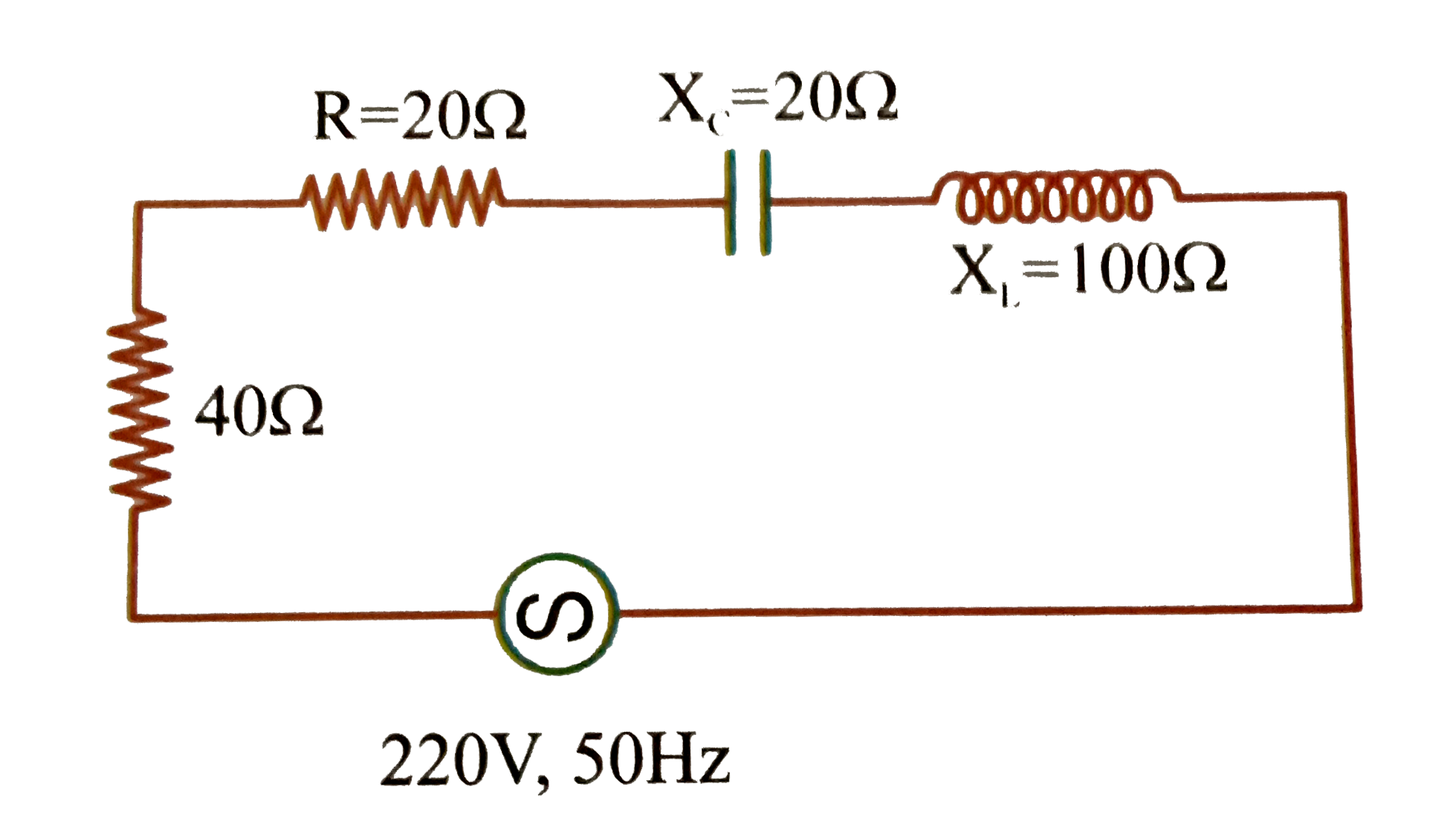
View SolutionThe power factor of the circuit shown in the figure is

View SolutionIn LCR circuit during resonance
View SolutionThe value of power factor coso in series LCR circuit at resonance is
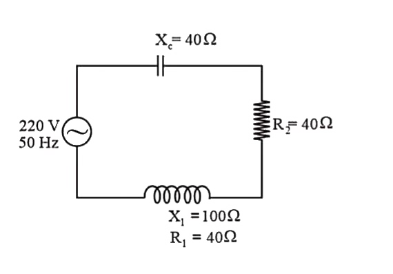
View SolutionPower factor of the circuit shown here is

View SolutionCalculate the power factor of the circuit shown in figure

View Solution
