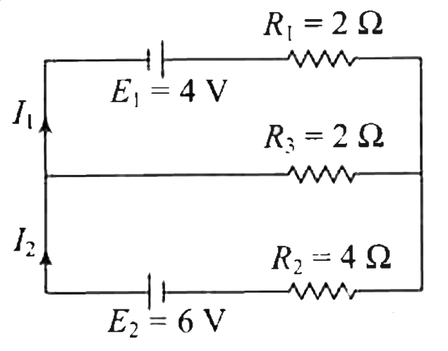
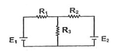
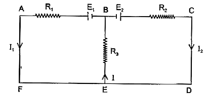
In the circuit shown below E−(1)=4.0V,R1=2Ω,E2=6.0V,R2=4Ω and R−(3)=2Ω. The current I1 is
1.6A
1.8A
2.25A
1A
The correct Answer is:B
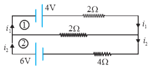
For "loop" (1)−2i1−2(i1−i2)+4=0⇒ 2i1–i2 = 2
For "loop"(2)−4i2−2(i1−i2)+6=0⇒ 3i1–i2 = 3
After "solving" equation (1) and (11) we get i1 = 1.8 A and i2 = 1.6 A.
Topper's Solved these Questions
- CURRENT ELECTRICITYBOOK - VMC MODULES ENGLISHCHAPTER - CURRENT ELECTRICITYEXERCISE - PRACTICE EXERCISE-1
5 Videos
- CURRENT ELECTRICITYBOOK - VMC MODULES ENGLISHCHAPTER - CURRENT ELECTRICITYEXERCISE - PRACTICE EXERCISE-2
5 Videos
- CURRENT ELECTRICITYBOOK - VMC MODULES ENGLISHCHAPTER - CURRENT ELECTRICITYEXERCISE - IN-CHAPTER EXERCISE-F
10 Videos
- CAPACITORSBOOK - VMC MODULES ENGLISHCHAPTER - CAPACITORSEXERCISE - JEE Advance ( Archive ) LEVEL 48
1 Videos
- DC CIRCUITBOOK - VMC MODULES ENGLISHCHAPTER - DC CIRCUITEXERCISE - JEE ADVANCED ARCHIVE
68 Videos
Similar Questions
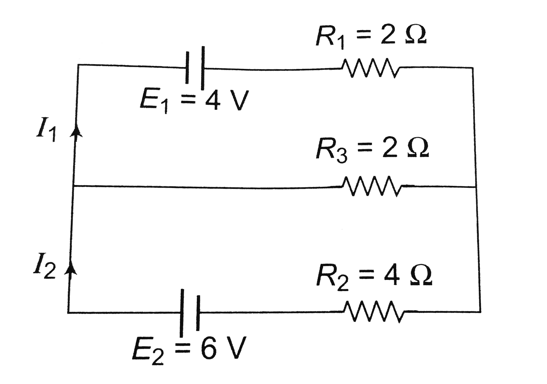
In the circuit shown below E1=4.0V,R1=2Ω,E2=6.0V,R2=4Ω and R3=2Ω. The current I1 is
View SolutionIn the following circuit ,E1=4V,R1=2Ω,
E2=6V,R2=2Ω,andR3=4Ω. Find the currents i1andi2
View SolutionIn the circuit shown, E1=7V,E2=7V,R1=R2=1Ω and R3=3Ω respectively. The current through the resistance R3
View SolutionIn the circuit shown, E1=7V,E2=7V,R1=R2=1Ω and R3=3Ω respectively. The current through the resistance R3

View SolutionIn the circuit shows in Fig E=15V, R1=1Ω, R2=1Ω, R3=2Ω, and L=1.5H. The currents flowing through R1,R2,and R3 are i1,i2, and i3, respectively.
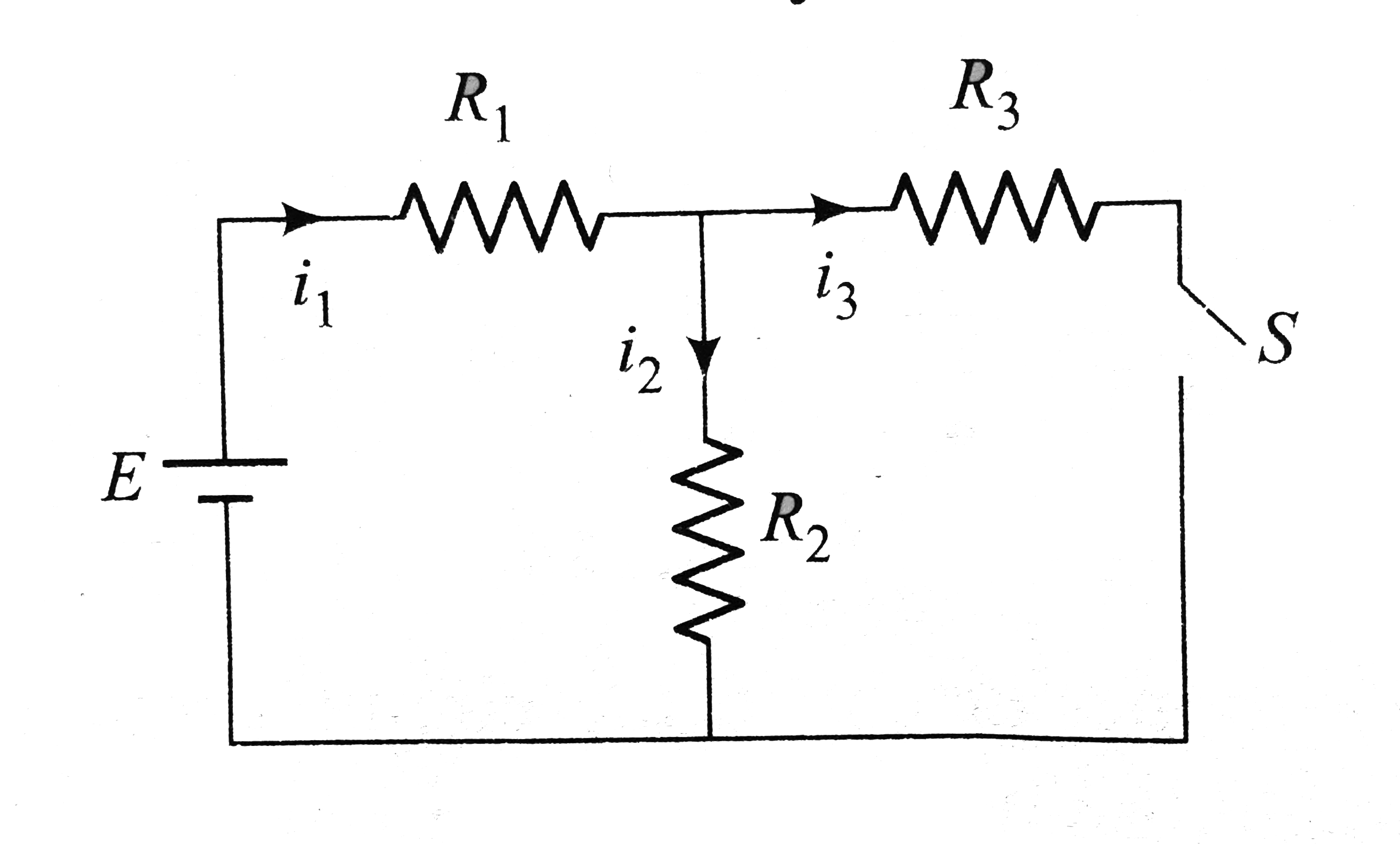
Immediately after connecting switch S,
View SolutionIn the circuit shows in Fig E=15V, R1=1Ω, R2=1Ω, R3=2Ω, and L=1.5H. The currents flowing through R1,R2,and R3 are i1,i2, and i3, respectively.
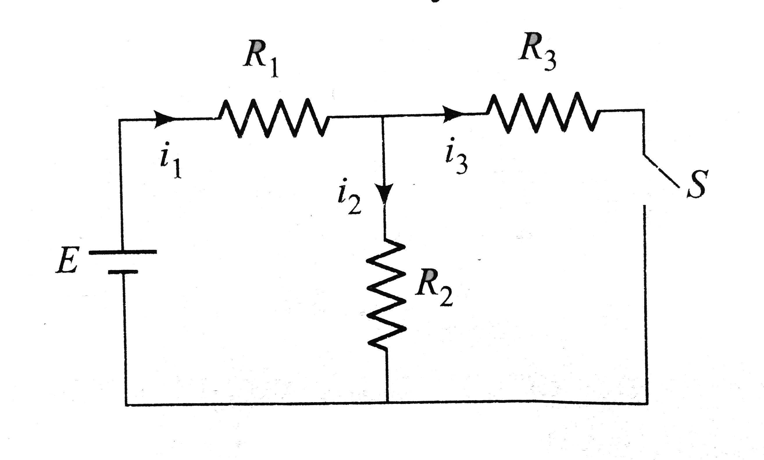
Immediately after tuning switch S on,
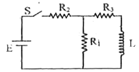
View SolutionFor the circuit shown E=50 V R1=10Ω,R2=20Ω,R3=30Ω L = 2.0 mH . The current through R1 and R2 are ________ . immediate after the switch is closed.
View SolutionIn the circuit shown below, E1=17V,E2=21V,R1=2Ω,R2=3ΩandR3=5Ω. Using Kirchhoff.s laws, find the currents flowing through the resistors R1,R2 and R3. (Internal resistance of each of the batteries is negligible.)
View SolutionIn the circuit shown in figure, R(1)=1Ω,R2=2Ω,C1=1μF,C2=2μF and E=6V. Calculate charge on each capacitor in steady state
View SolutionIn the circuit shown in fig. R1=10Ω,R2=5Ω,C1=1μF,C2=2μF, and E =6V. Calculate the charge on each capactor in the stedy state.
View Solution
