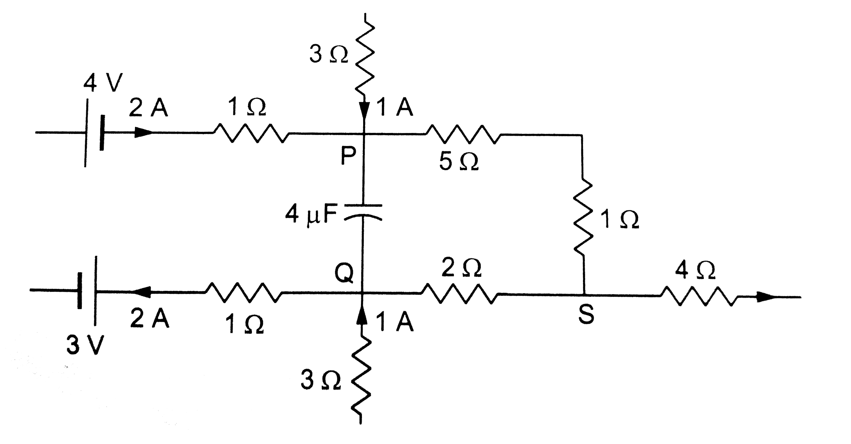
A part of a circuit in steady state along with the currents flowing in the branches,the values of resistances,etc, is shown in figure.Calculate the energy stored in the capacitor.
6×10⁻⁴J
8×10⁻⁴J
16×10−4J
Zero
The correct Answer is:B
Applying Kirchhoff.s first law at junctions A and B respectively we have 2+1−i1 = 0
i.e, i1 = 3A and i2+1−2−0 i.e., i2= 1A
Now applying Kirchhoff.s second law to the mesh ADCBA treating capacitor as a seat of emf V in open circuit −3×5–3×1–1×2+V=0 ie. V=(VA−VB) = 20 V
So, energy stored in the capacit U=12CV2=12(4×10−6)×(20)2=8×10⁻⁴J
Topper's Solved these Questions
- BOOK - VMC MODULES ENGLISHCHAPTER - CURRENT ELECTRICITYEXERCISE - PRACTICE EXERCISE-15videos
CURRENT ELECTRICITY
- BOOK - VMC MODULES ENGLISHCHAPTER - CURRENT ELECTRICITYEXERCISE - PRACTICE EXERCISE-25videos
CURRENT ELECTRICITY
- BOOK - VMC MODULES ENGLISHCHAPTER - CURRENT ELECTRICITYEXERCISE - IN-CHAPTER EXERCISE-F10videos
CURRENT ELECTRICITY
- BOOK - VMC MODULES ENGLISHCHAPTER - CAPACITORSEXERCISE - JEE Advance ( Archive ) LEVEL 481videos
CAPACITORS
- BOOK - VMC MODULES ENGLISHCHAPTER - DC CIRCUITEXERCISE - JEE ADVANCED ARCHIVE68videos
DC CIRCUIT
Similar Questions
A part of a circuit in steady state with the currents flowing in a braches , the value of resistance etc is shown in the figure.
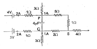
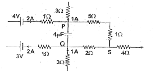
Current in the 2Ω resistor isView SolutionA part of a circuit in steady state with the currents flowing in a braches , the value of resistance etc is shown in the figure.
Potential difference between points P and Q.isView SolutionThe capacitors shown in figure. Is in steady state. The energy stored in the capacitor is
 View Solution
In the circuit as shown in figure, energy stored in capacitor at steady state is
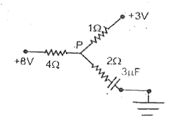
View SolutionThe energy stored in the capacitor in the steady state is
 View Solution
In the circuit shown in figure charge stored in the capacitor of capacity 5μf is
 View Solution
The charge on the capacitor in steady state in the circuit shown is
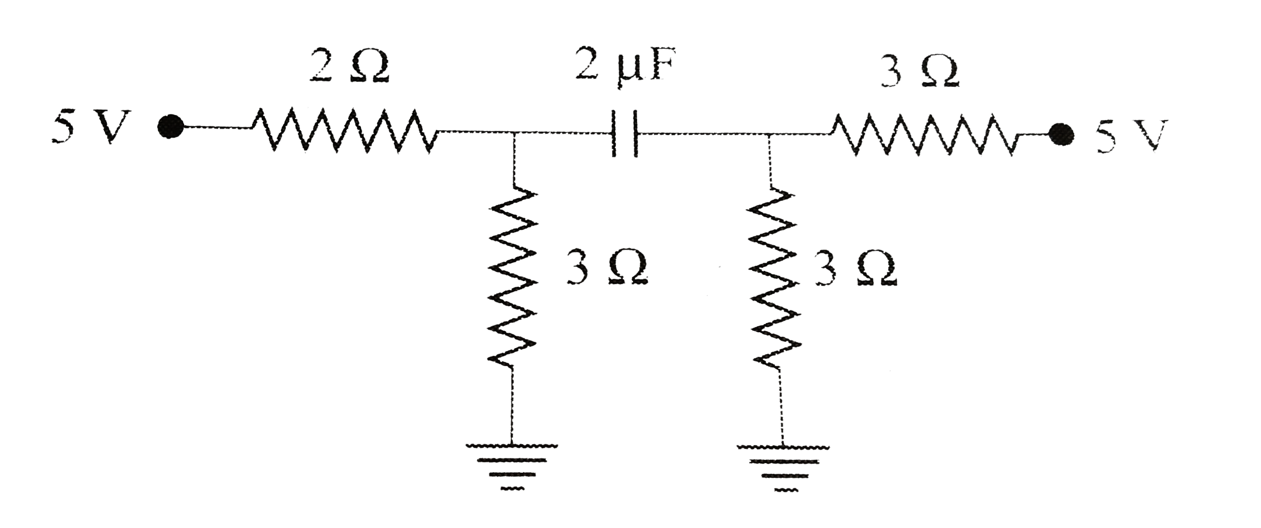 View Solution
Find the current through the resistance in the circuits shown in figure
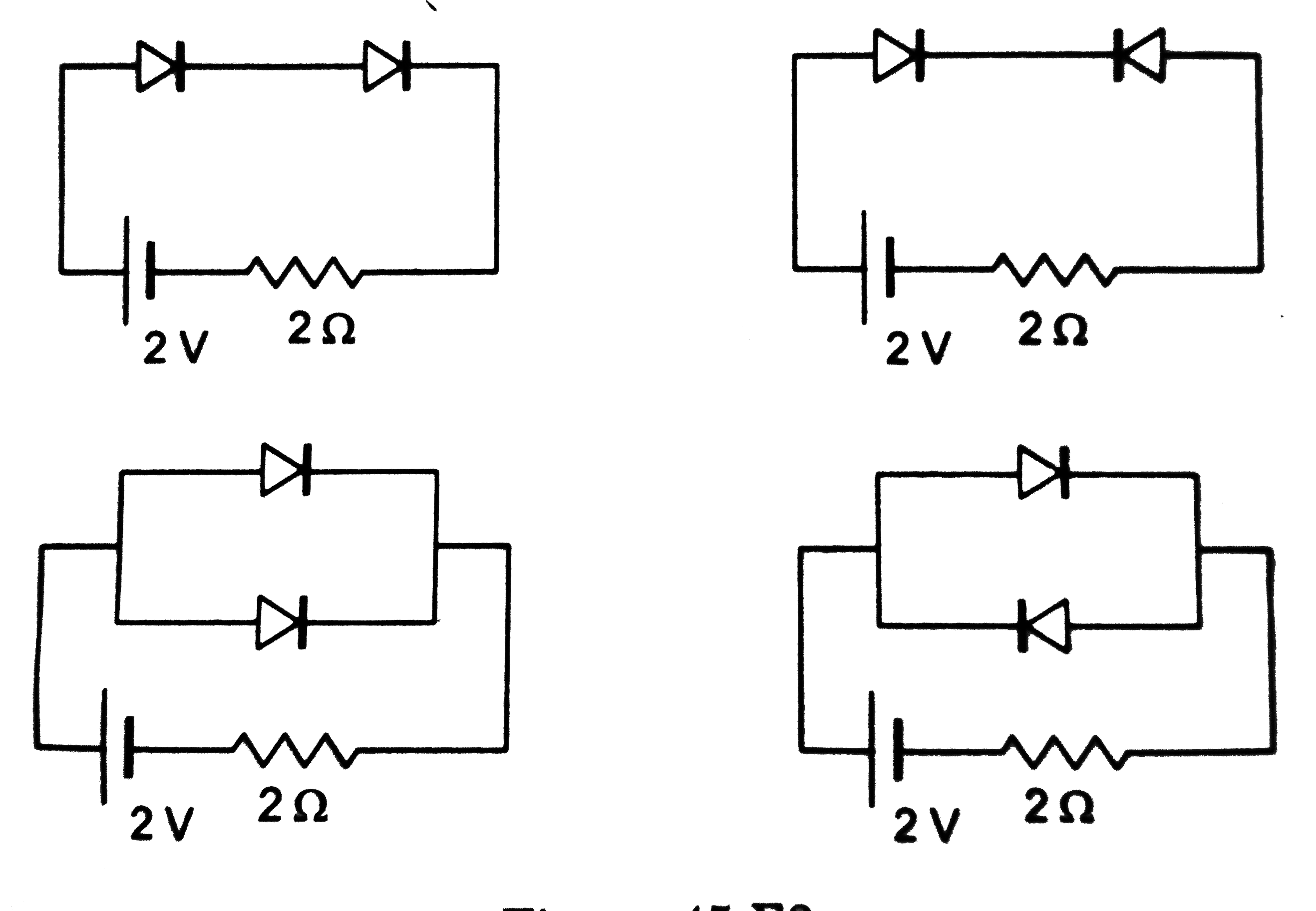 View Solution
In the steady state of the circuit shown in the figure the ratio of energy stored in the inductor to th energy stored in the capacitor is 1000000.
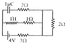 View Solution
In the circuit shown in figure 3.141, find the energy stored in 4μF capacitor in steady state.
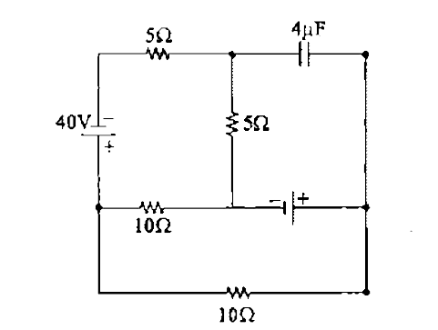 View Solution

