The following diagram shows the circuit for the comparision of e.m.f. of the cells. The circuit can be corrected by:-
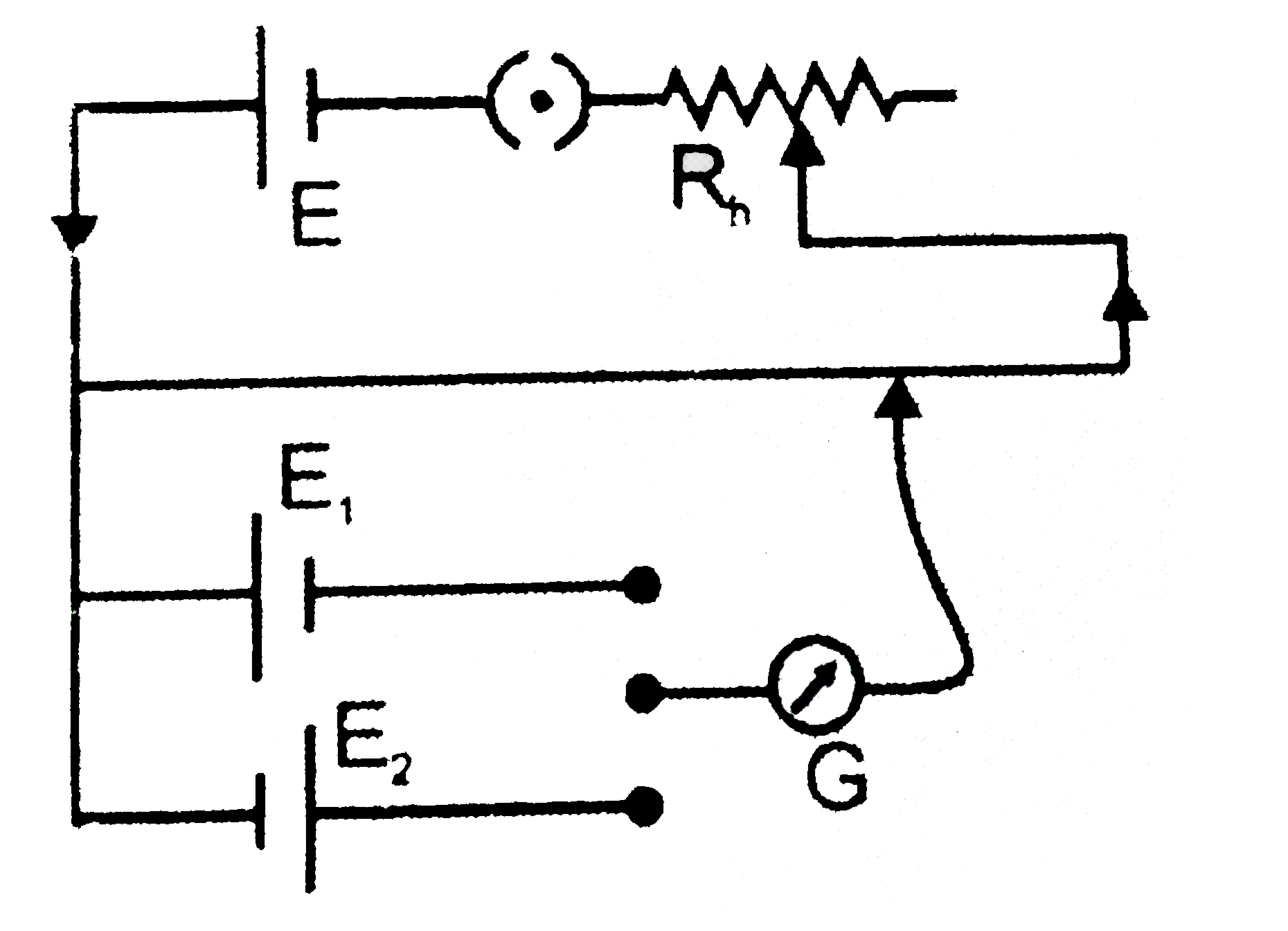
reversing the terminals of E
reversing the terminals of
reversing the terminals of
reversing the current in Rh
The correct Answer is:C
Step by step video & image solution for The following diagram shows the circuit for the comparision of e.m.f. of the cells. The circuit can be corrected by:- by Physics experts to help you in doubts & scoring excellent marks in Class 12 exams.
Updated on:21/07/2023Topper's Solved these Questions
- CURRENT ELECTRICITYBOOK - VMC MODULES ENGLISHCHAPTER - CURRENT ELECTRICITYEXERCISE - IN-CHAPTER EXERCISE-F
10 Videos
- CURRENT ELECTRICITYBOOK - VMC MODULES ENGLISHCHAPTER - CURRENT ELECTRICITYEXERCISE - IN-CHAPTER EXERCISE-D
9 Videos
- CAPACITORSBOOK - VMC MODULES ENGLISHCHAPTER - CAPACITORSEXERCISE - JEE Advance ( Archive ) LEVEL 48
1 Videos
- DC CIRCUITBOOK - VMC MODULES ENGLISHCHAPTER - DC CIRCUITEXERCISE - JEE ADVANCED ARCHIVE
68 Videos
Similar Questions
In the circuit diagram shown
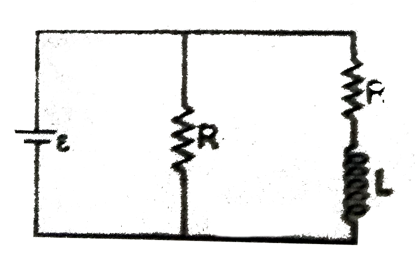
View SolutionStudy the following circuit diagram and mark the correct options.
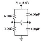
View SolutionThe following diagram (Fig) shows four circuits A, B, C and D. Each circuit has a cell and a torch bulb. Name the circuits in which the bulb will glow? Give reason to your answer.
View SolutionIn the following diagram the deflection in the galvanometer in a potentiometer circuit is zero. Then:-
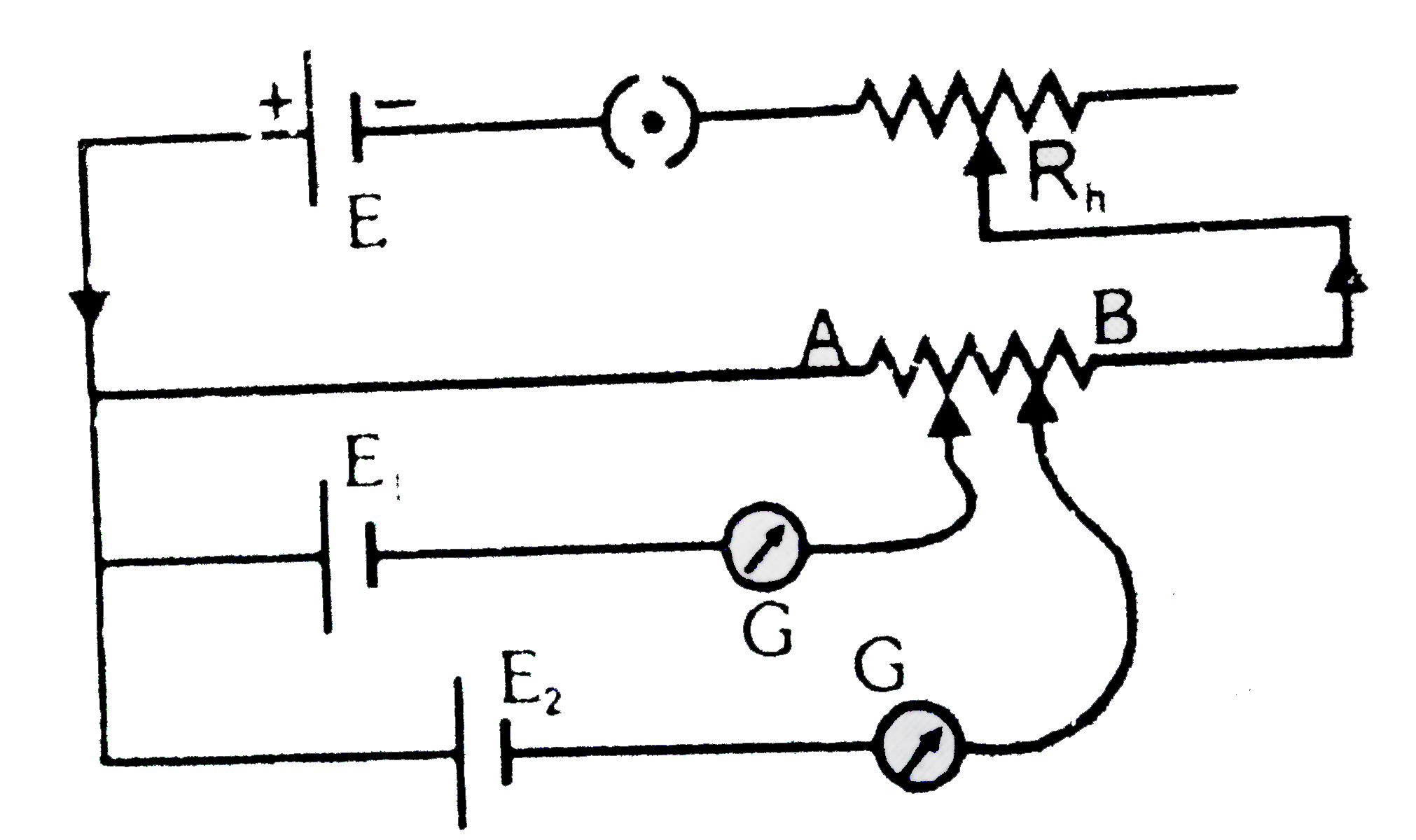
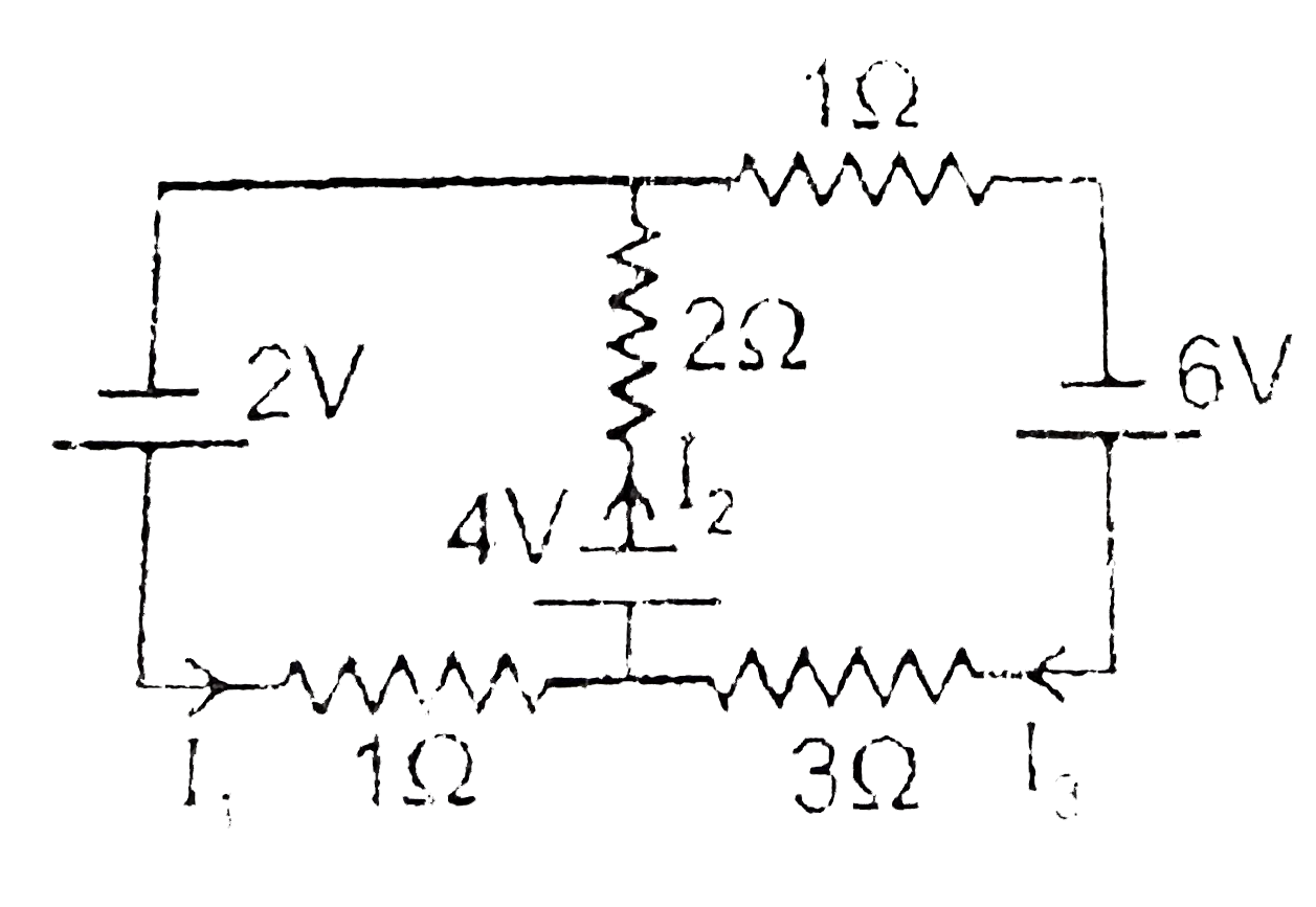
View SolutionWhich one of the following equation is correct for the circuit shown. The currents in each branch of circuit are indicated and all three cells are ideal
View SolutionThe diagram alongside shows a circuit with the key k open. Calculate :
the resistance of the circuit when the key k is closed.
View Solution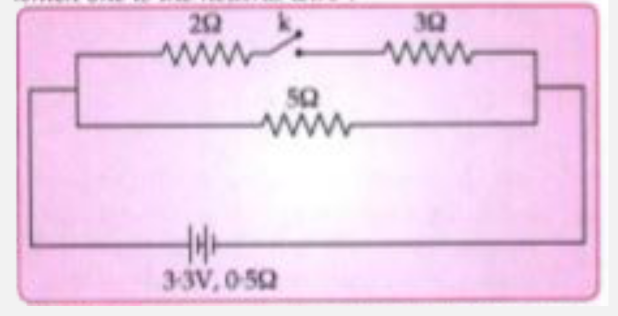
The diagram above shows a circuit with the key k open. Calculate :
the resistance of the circuit when the key k is closed.
View SolutionThe diagram alongside shows a circuit with the key k open. Calculate :
the resistance of the circuit when the key k is open.
View SolutionThe temperature coefficient of e.m.f of a cell can be given by :
View SolutionIn the circuit diagram shown in Figure,
 .
.
View Solution
