Figure shows two electrical circuits.
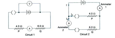
The batteries in circuit 1 and circuit 2 are identical.
(a) Put ticks in the table below to describe the connections of the two resistors P and Q.

(b) The resistor P and Q are used as small electrical heaters.
State two advantages of connecting them as shown in circuit 2.
(c) In circuit 1, the ammeter reads 1.2A when the switch is closed.
Calculate the reading of the voltmeter in this circuit.
(d) The two switches in circuit 2 are closed. Calculate the combined resistance of the two resistors in this circuit.
(e) When the switches are closed in circuit 2, ammeter 1 reads 5 A and ammeter 2 reads 2A. Calculate
(i) the current in resistor P,
(ii) the power supplied to resistor Q,
(iii) the energy transformed in resistor Q in 300s.
Text Solution
(a) 
(b) (i) If one electrical heater stops working due to some defect then other keeps working normally.
(ii) Each electrical appliance (heater) gets the same voltage (220 V) as that of the power supply line.
(c) Effective resistance, R=4+6=10Ω
Current, I = 1.2 A
V=IR=1.2×10=12V
Voltmeter reading = 12 V
(d) Combined resistance,
Rp=R1R2R1+R2=4×64+6=2410=2.4Ω
(e) Current I = 5A
I2=2A
(i) The current in resistor P=I1=I−I2=5A−2A=3A
(ii) The power supplied to resistor, Q=VI=12×2=24W
(iii) The energy transformed in resistor Q in 300s=E=P×t=24×300s=7200J
|
Topper's Solved these Questions
- ELECTRICITYBOOK - VK GLOBAL PUBLICATIONCHAPTER - ELECTRICITYEXERCISE - NUMERICALS
2 Videos
- ELECTRICITYBOOK - VK GLOBAL PUBLICATIONCHAPTER - ELECTRICITYEXERCISE - NUMERICALS (RESISTANCE AND RESISTIVITY)
23 Videos
- ELECTRICITYBOOK - VK GLOBAL PUBLICATIONCHAPTER - ELECTRICITYEXERCISE - SHORT ANSWER QUESTION-II
8 Videos
- LIGHT-REFLECTION AND REFRACTIONBOOK - VK GLOBAL PUBLICATIONCHAPTER - LIGHT-REFLECTION AND REFRACTIONEXERCISE - PROFICIENCY EXERCISE (Long Answer Questions)
5 Videos
Similar Questions
Knowledge Check
A student stes up an electric circuit shown here for finding the equivalent resistance of two resistors in series :
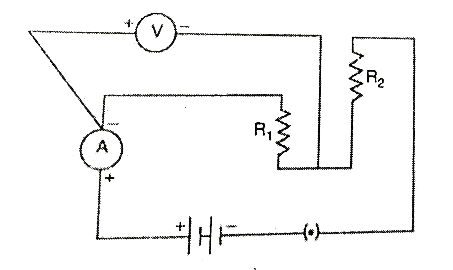
In this circuit, the :Aresistors have been connected correctly but the voltmeter has been wrongly connectedBresistors have been connected correctly but the ammeter has been wrongly connectedCresistors as well as the voltmeter have been wrongly connectedDresistors as well as the ammeter have been wrongly connectedTwo ideal diodes are connected to a battery as shown in the circuit. The current supplied by the battery is
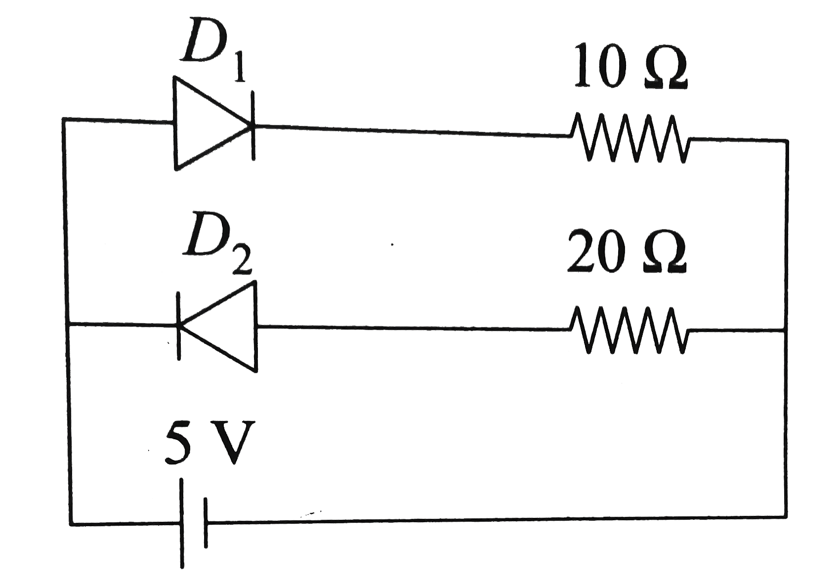 A0.75 ABzeroC0.25 AD0.5 A
Two ideal diodes are connected to a battery as shown in the circuit. The current supplied by the battery is
 A0.5AB0.75ACzeroD0.25A
In an electric circuit shown alongside, find
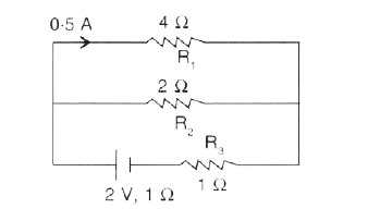
current in resistor 2Ω
View SolutionGiven below are two electric circuits A and B
Calculate the ratio of power factor of the circuit B to the power factor of circuit A.

View SolutionGiven below are two electric circuits A and B
Calculate the ratio of power factor of the circuit B to the power factor of circuit A.

View SolutionThree resistors are connected to a 6 V battery as shown in the figure given below :
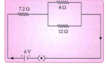
Calculate :
total current in the circuit.
View SolutionTwo ideal diodes are connected to a battery as shown in the circuit. The current supplied by the battery is

View Solution
