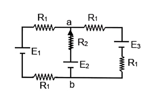
In the given network of ideal cells and resistors, R1=1.0Ω,R2=2.0Ω,E1=2V and E2=E3=4V. The potential difference between the point a and b is
83V
103V
94V
134V
The correct Answer is:B
Step by step video & image solution for In the given network of ideal cells and resistors, R_(1) = 1.0 Omega, R_(2) = 2.0 Omega, E_(1) = 2V and E_(2) = E_(3) = 4V. The potential difference between the point a and b is by Physics experts to help you in doubts & scoring excellent marks in Class 12 exams.
Updated on:21/07/2023Similar Questions
For the circuit shown, with R1=1.0Ω,R2=2.0Ω,E1=2V and E2=E3=4V, the potential difference between the points 'a' and 'b' is approximately (in V):
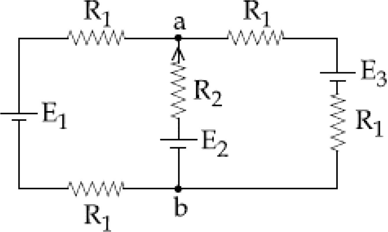
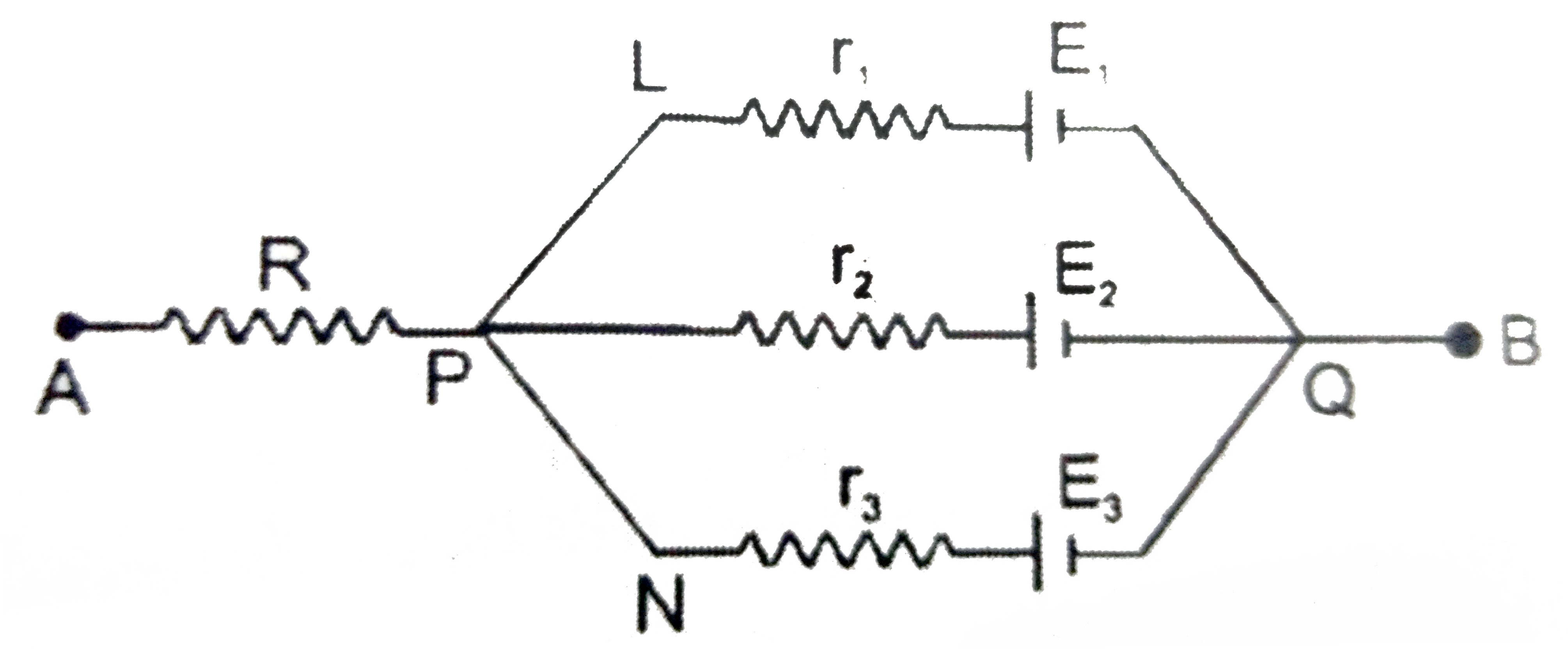
View SolutionCalculate the effective resistance between the points A and B in the circuit shown in Fig.
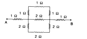
View SolutionIn the circuit shown here, E1=E2=E3=2V and R1=R2=4ohms. The current flowing between point A and B through battery E2 is
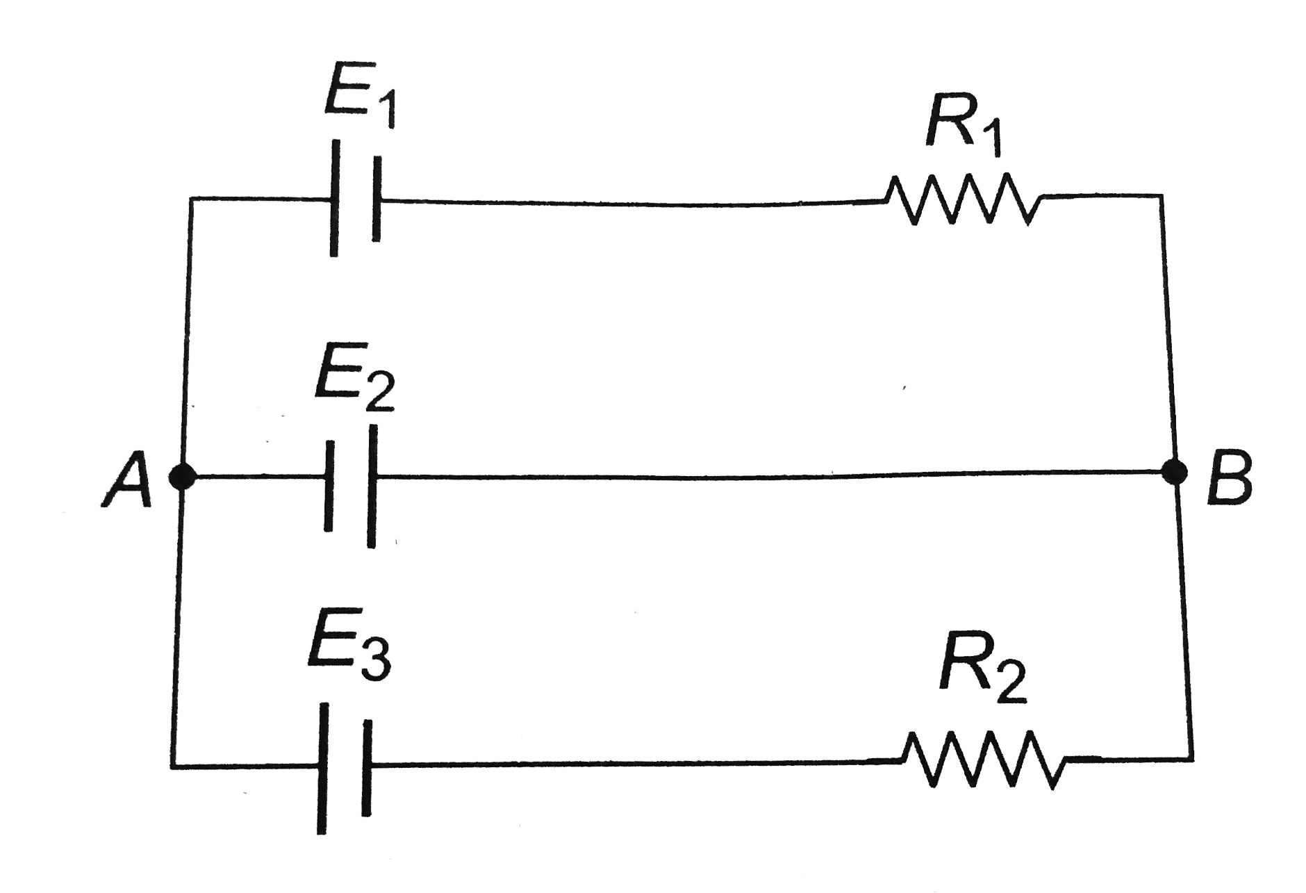
View SolutionIn the circuit shown in figure ,(ε)1=3V,(ε)2=2V,(ε)3=1Vandr1=r2=r3=1(Ω).Find the potential difference between the points A and B and the current through each branch.
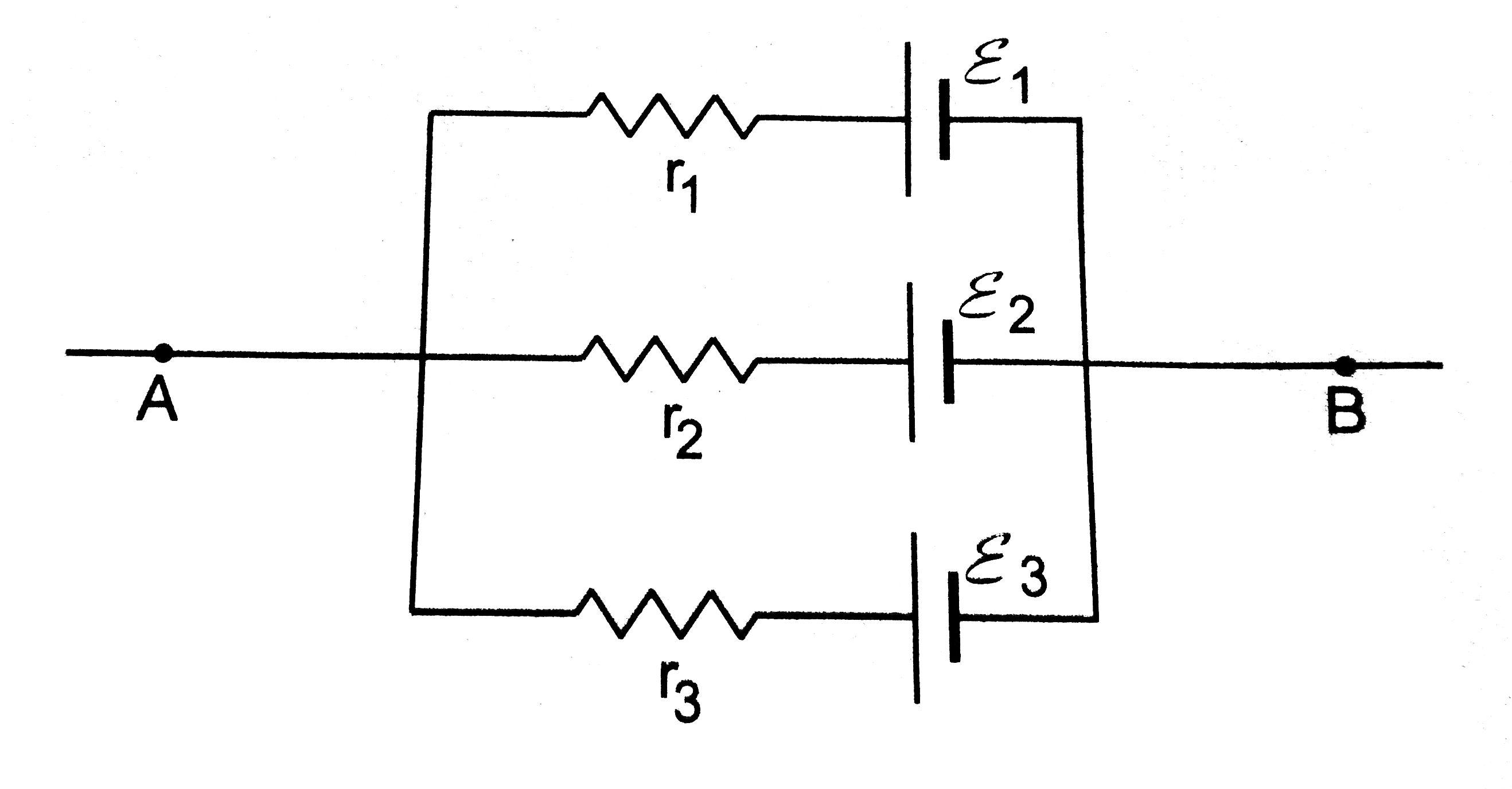
View SolutionIn the circuit shown in fig. E1=3 volt,E2=2 volt,E3=1 vole and R=r1=r2=r3=1ohm.
(i) Find potential difference in Volt between the points A and B with A & B unconnected.
(ii) If r2 is short circuited and the point A is coneted to point B through a zero resistance wire, find the current through R in ampere.
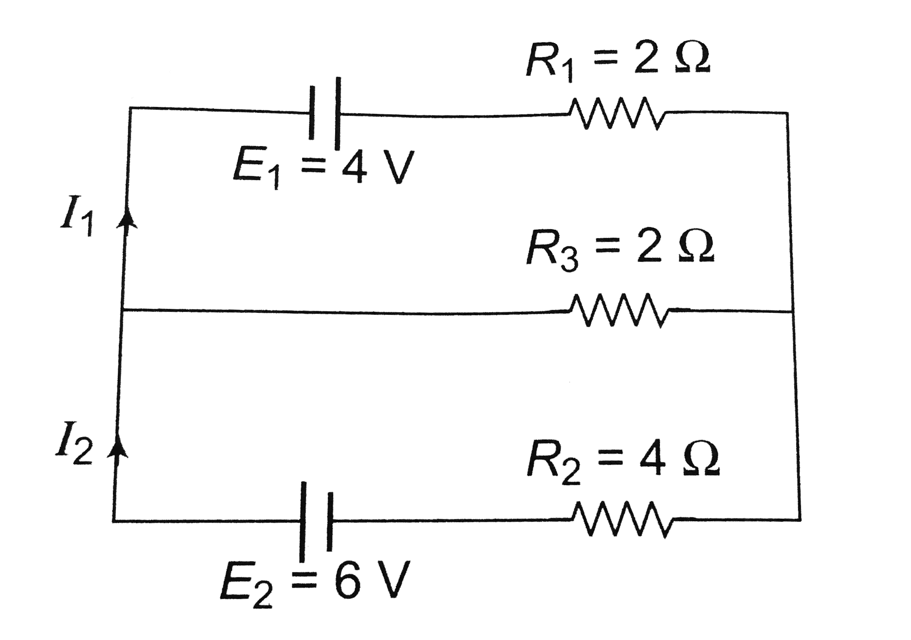
View SolutionIn the circuit shown below E1=4.0V,R1=2Ω,E2=6.0V,R2=4Ω and R3=2Ω. The current I1 is
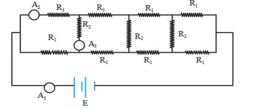
View SolutionIn the given circuit, R1 = 10Ω R2=6Ω and E = 10V, then correct statement is
View SolutionIn the circuit in figure E1=3V,E2=2V,E3=1V and R=r1=r2=r3=1Ω
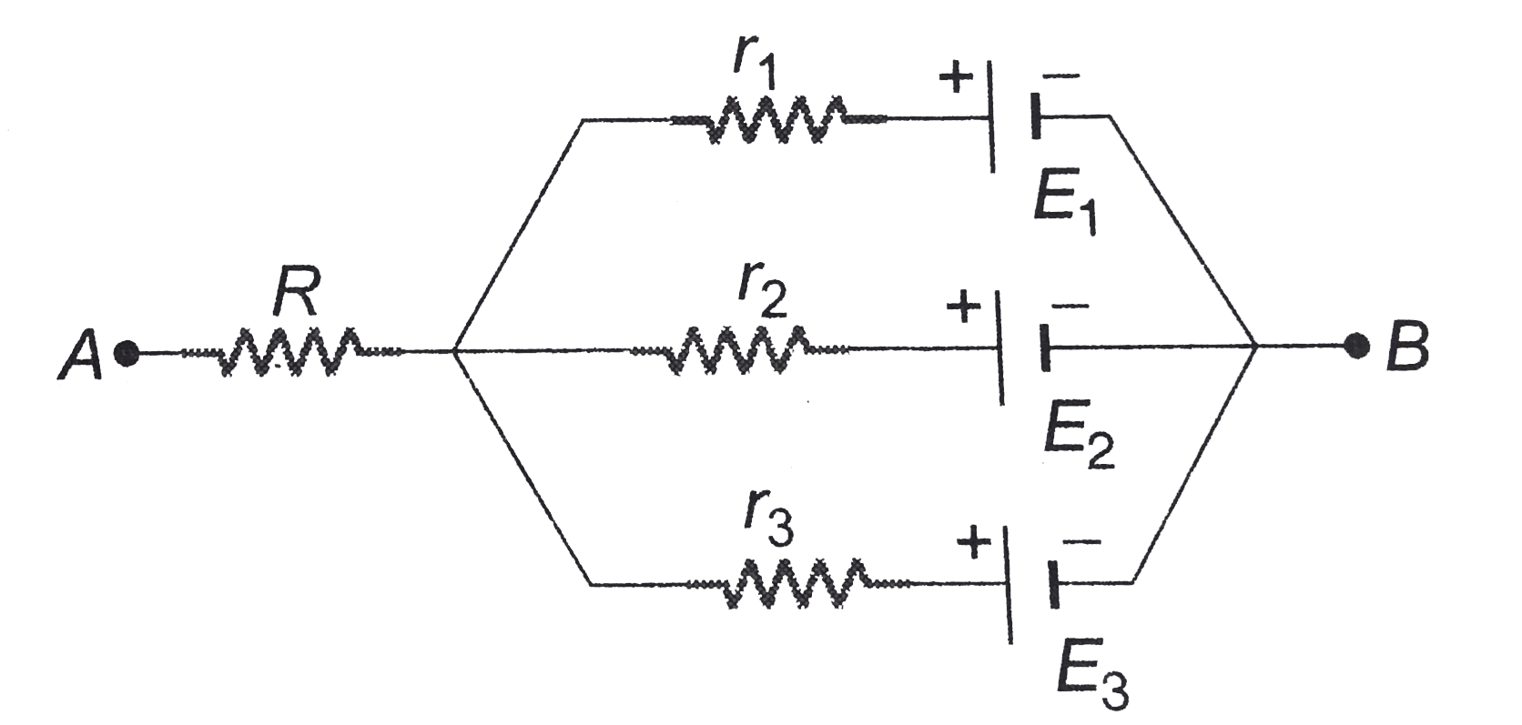
Find the potential differece between the points A and B and the currents through each branch.
View SolutionThe circuit in Fig. shows two cells connected in opposition to each other. Cell E1 is of emf 6V and internal resistance 2Ω, the cell E2 is of emf 4V sand internal resistance 8ω. Find the potential difference between the points A and B.

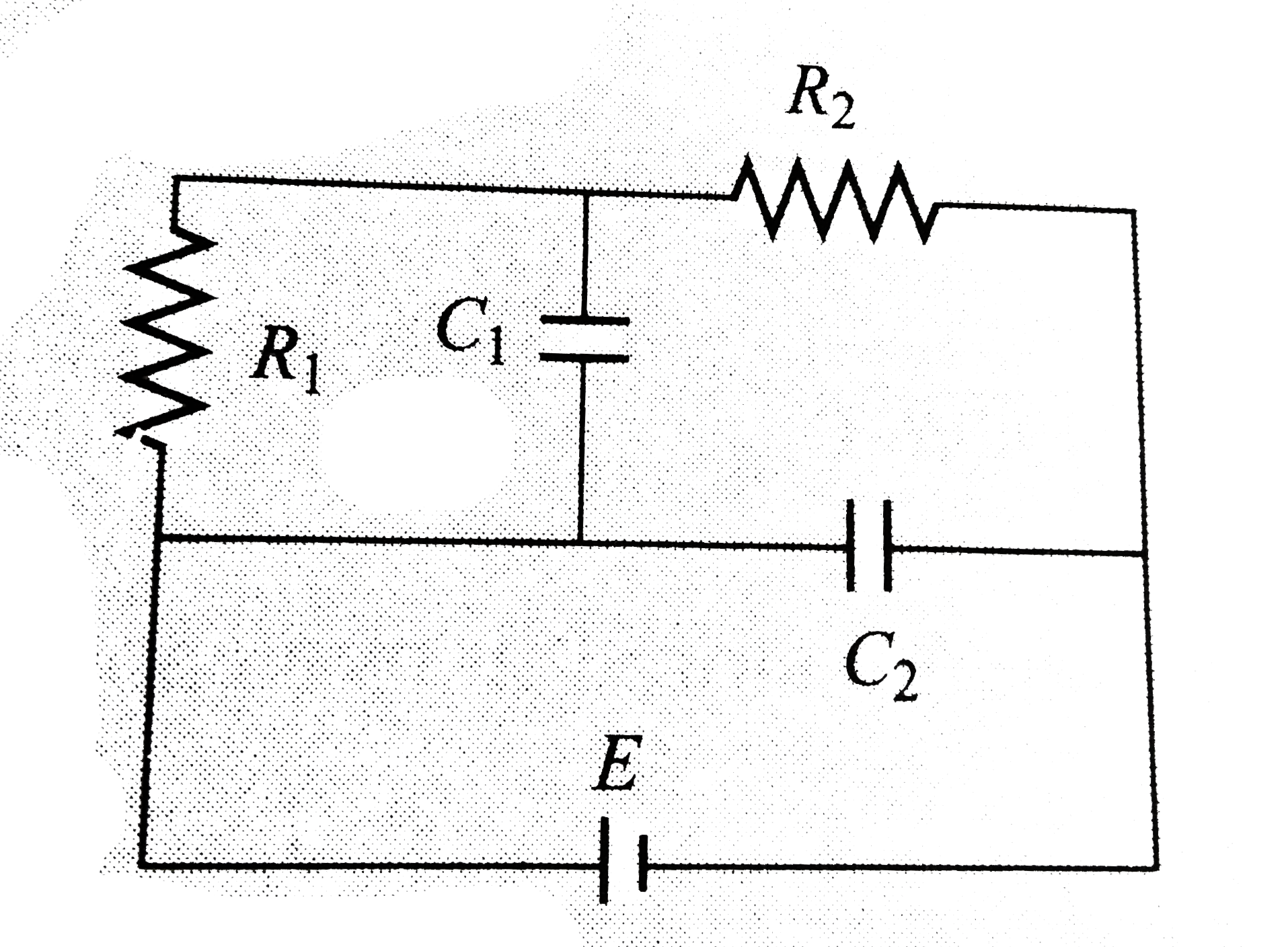
View SolutionIn the circuit shown in fig. R1=10Ω,R2=5Ω,C1=1μF,C2=2μF, and E =6V. Calculate the charge on each capactor in the stedy state.
View Solution
