In the figure shown , RB=500kΩ,RC=8kΩ,VBB=10.6VandVCC=20V . The current amplification factor β=100andVBE=0.6 V . Mark the incorrect statement .
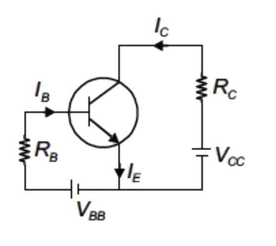
IB=20μA
VCB=3.4V
VCB=2.8V
the transistor is in active region
The correct Answer is:C
Step by step video & image solution for In the figure shown , R_B=500kOmega, R_C = 8 kOmega, V_("BB")=10.6V and V_("CC") = 20V . The current amplification factor beta=100 and V_("BE")=0.6 V . Mark the incorrect statement . by Physics experts to help you in doubts & scoring excellent marks in Class 12 exams.
Updated on:21/07/2023Similar Questions
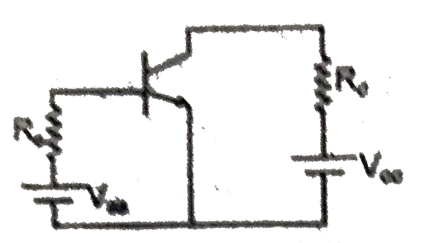
In the figure shown RB=500KΩ,RC=8KΩ,VBB=10.6V and VCC=20V. The current amplification factor of the transistor is 100 and VBE=0.6 volt then which of the following is false?
View SolutionIn the circuit diagram shown, R=10ω,L=5mH,E=10 V and i=1A. The current is decreasing at the reate of 103A/S. Then (VA−VB)at this instant is :

View Solution
Knowledge Check
An n-p-n transistor in a common-emitter mode is used as a simple voltage-amplifier with a collector current of 4 mA. The terminals of a 8 V battery is connected to the collector through a load-resistance RL and to the base through a resistance RB. The collector-emitter voltage VCE=4V, the base-emitter voltage VBE=0.6V and the current amplification factor βdc=100. Then
ARL=1kΩ,RB=185kΩBRL=2kΩ=RBCRL=2kΩ,RB=15kΩDRL=185kΩ,RB=1kΩ
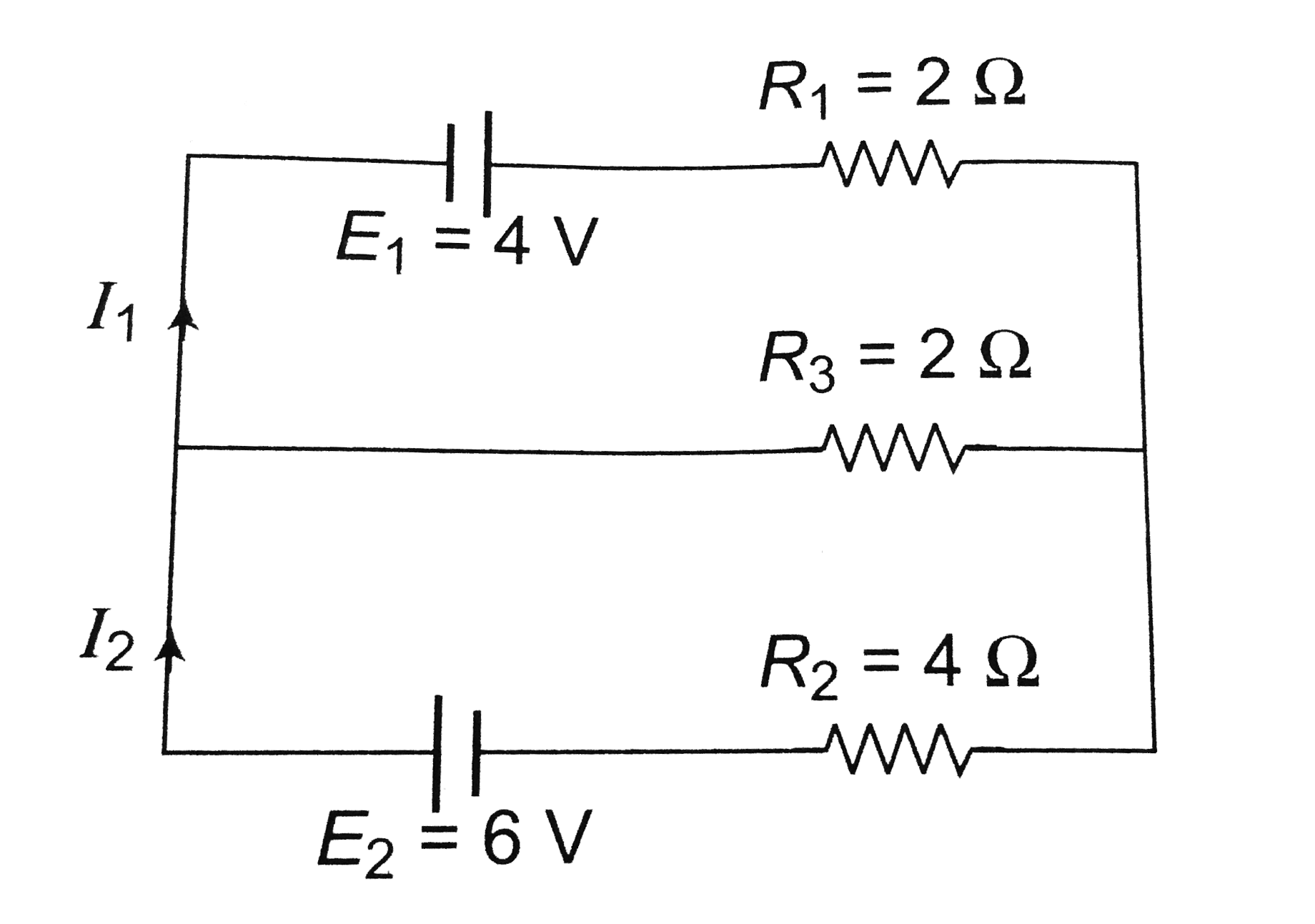
In the circuit shown below E1=4.0V,R1=2Ω,E2=6.0V,R2=4Ω and R3=2Ω. The current I1 is
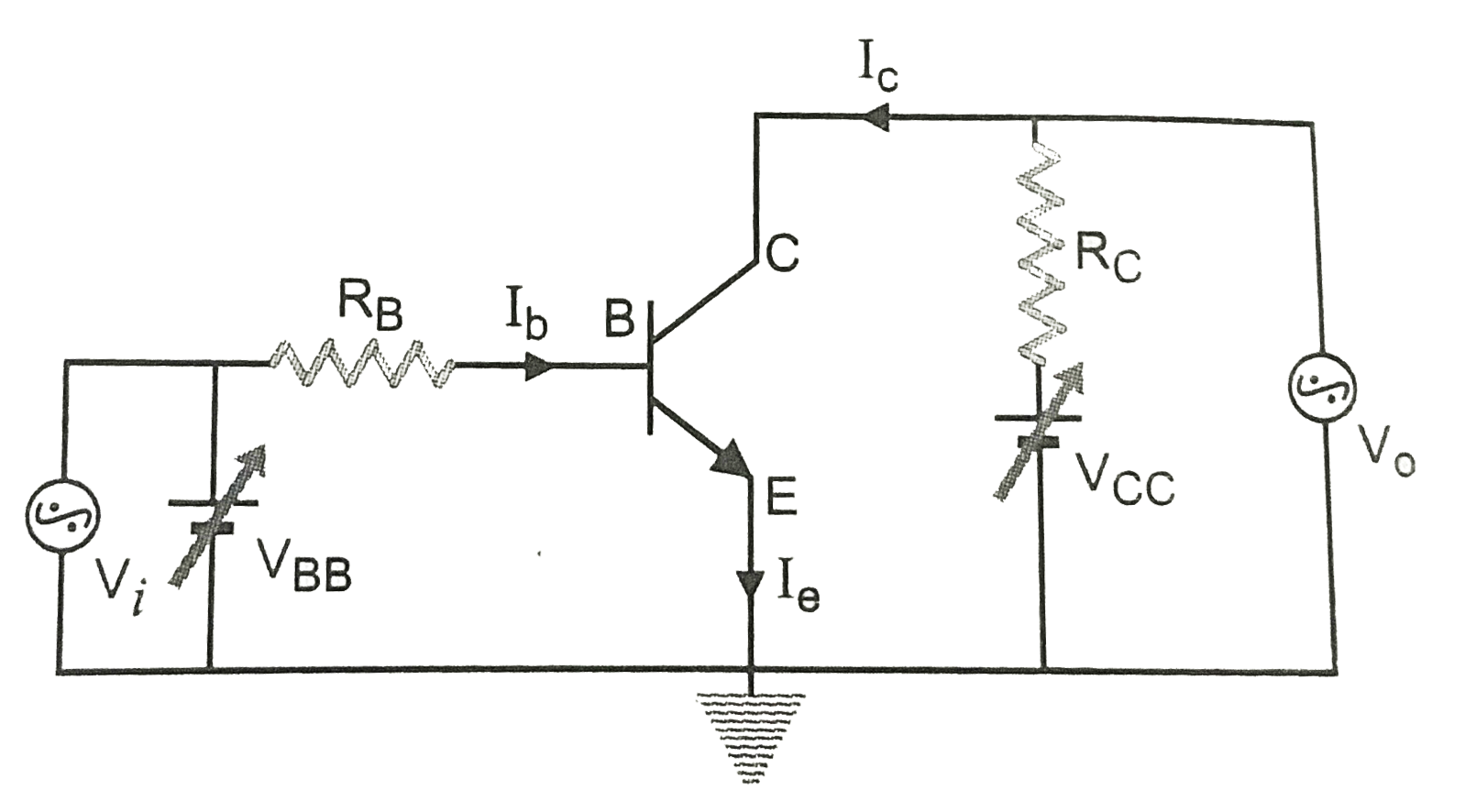
View SolutionIn common emitter transistor as shown in Fig., the VBB supply can be varied from 0 V to 5.0V. The Si. Transistor has βac=250 and RB=100kΩ,Rc=1kΩ,VCC=5.0V. Assume that when the transistor is saturated, VCE=0V and VBE=0.8V. Calculate the minimum base current, for which the transistor will reach saturation. Hence, determine Vi when the transistor is 'switched on' find ranges of Vi for which the transistor is switched off and switched on.
View SolutionAn n-p-n transistor in a common - emitter mode is used as a simple voltage amplifier with a collector current of 4 mA. The positive terminal of a 8 V battery is connected to the collector through a load resistance RL and to the base through a resistance RB . The collector - emitter voltage VCE=4V , the base - emitter voltage VBE=0.6V and the current amplification factor β=100 . Calculate the values of RL and RB .
View SolutionFor a common emitter transistor amplifier, the audio signal voltage across the collector resistance (Rc) of 2kΩ is 2 V. If the current amplification factor (β) of the transistor is 100, calculate the input signal voltage (VBE) and base current (Ig) for base resistance of 1kΩ.
View SolutionIn the circuit diagram shown in Figure, R=10Ω,L=5H,E=20v,i=2A. This current is decreasing at a rate of −1.0A/s. Find Vab at this instant.

View SolutionIn the circuit diagram shown in Figure, R=10Ω,L=l5H,E=20v,i=2A. This current is decreasing at a rate of −1.0A/s. Find Vab at this instant.

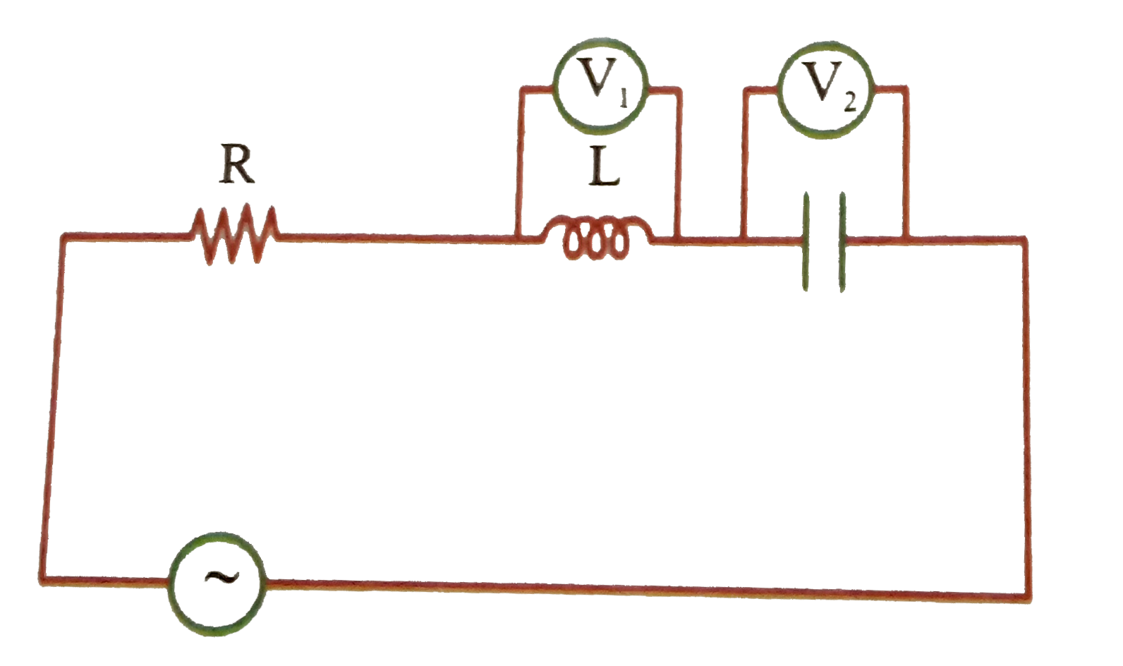
View SolutionIn the figure shown R=100ΩL=2πH and C=8πμF are connected in series with a.c source of 200 volt and frequency 'f'. V1 and V2 are two hot-wire voltmeters. If the readings of V1 and V2 are same then:
View Solution
