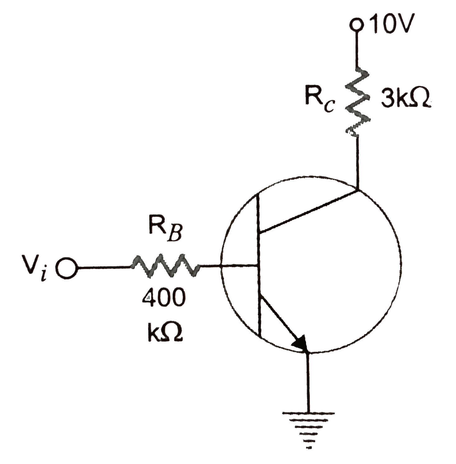
In the circuit shown in the figure, the input voltage Vi is 20V, VBE=0 and VCE=0. The values of IB, IC and β are given by
A
¯¯¯¯¯¯¯¯A.B+A.B
B
A.¯¯¯B+¯¯¯A.B
C
¯¯¯¯¯¯¯¯A.B
D
¯¯¯¯¯¯¯¯¯¯¯A+B
Video Solution
Text Solution
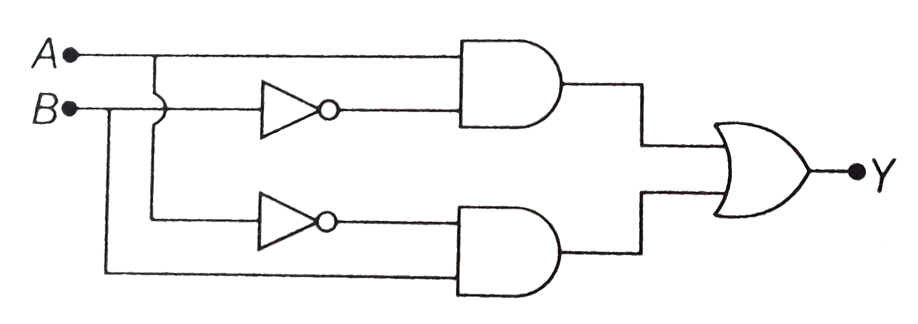
According to the question, the figure of combination of gates in terms of inputs and outputs can be given as

Thus, Y=A.¯¯¯B+¯¯¯A.B
|
Updated on:21/07/2023
Topper's Solved these Questions
- BOOK - DC PANDEYCHAPTER - SOLVED PAPERS 2018EXERCISE - AIIMS22videos
SOLVED PAPERS 2018
- BOOK - DC PANDEYCHAPTER - SOLVED PAPERS 2018EXERCISE - Assertion and Reasons10videos
SOLVED PAPERS 2018
- BOOK - DC PANDEYCHAPTER - SOLVED PAPER 2017EXERCISE - Solved papers 2017(JIPMER)32videos
SOLVED PAPER 2017
- BOOK - DC PANDEYCHAPTER - WAVE OPTICSEXERCISE - For JEE Advanced E. Integer Type Questions13videos
WAVE OPTICS
Similar Questions
Knowledge Check
- Question 1 - Select One
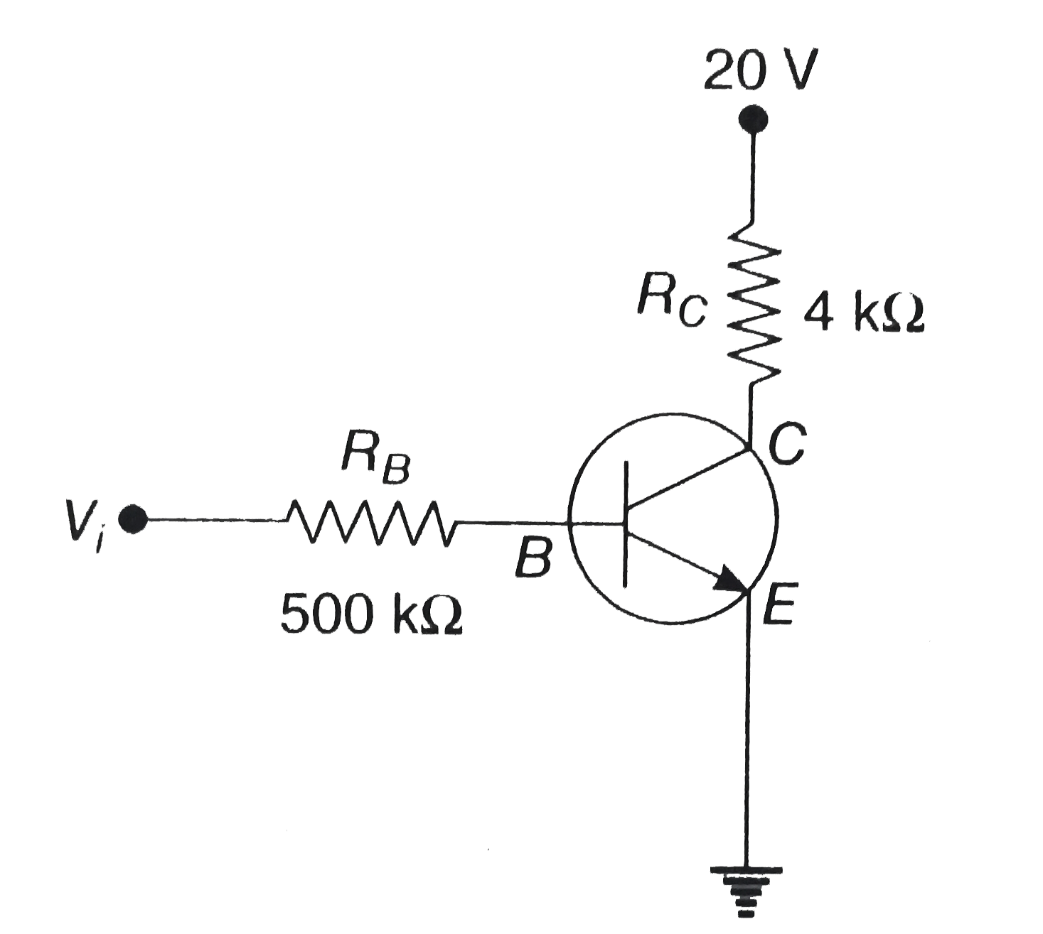
In the circuit shown in the figure, the input voltage Vi is 20V,VBE=0 and VCE=0. The values of IB,IC and β are given by:
 AIB=40μA,IC=10mA,β=250BIB=25μA,IC=5mA,β=200CIB=20μA,IC=5mA,β=250DIB=40μA,IC=5mA,β=125
 - Question 2 - Select One
In the circuit shows in the figure, the input voltage
Vi is 20 V, VBE=0 and VCE=0. The values of lB,lC and β are given by
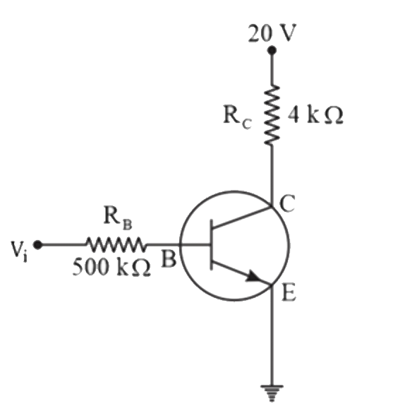 AlB=20μA,lC=5mA,β=250BlB=25μA,lC=5mA,β=200ClB=40μA,lC=10mA,β=250DlB=40μA,lC=5mA,β=125
 - Question 3 - Select One
In the circuit shown in figure the maximum output voltage V0 is
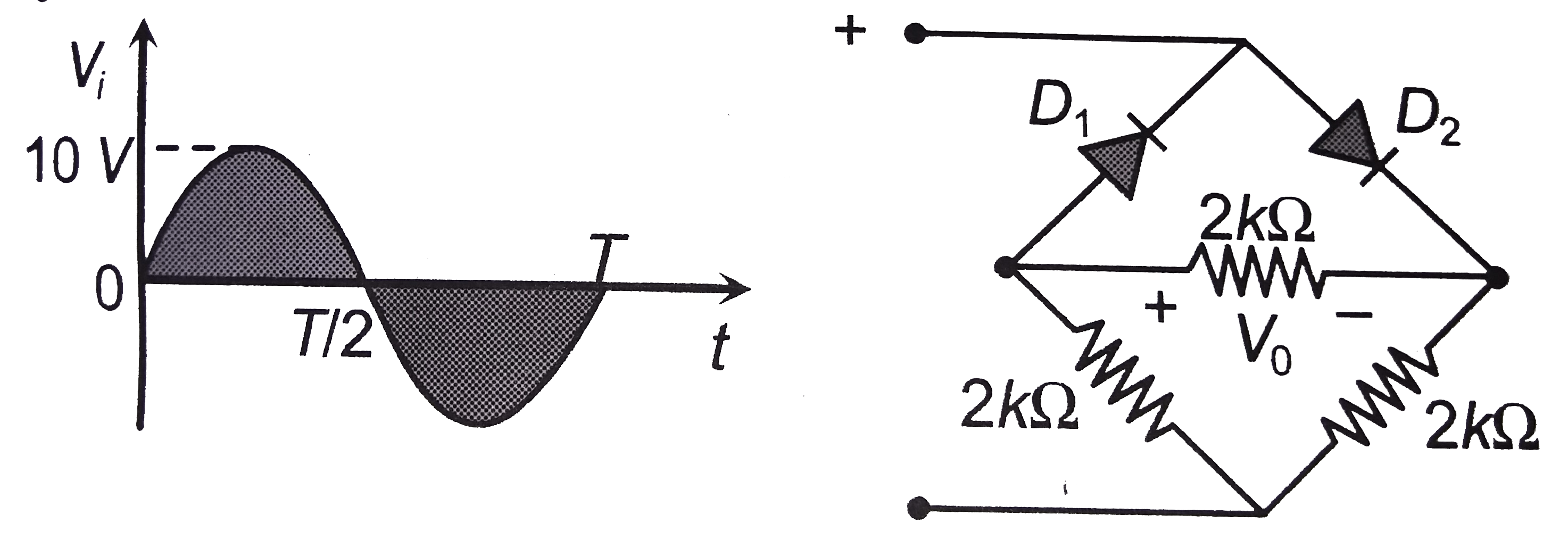 A0VB5VC10VD5√2V
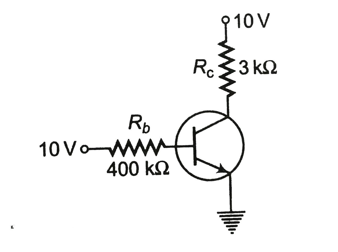
In the circuit shown in figure when the input voltage of the base resistance is 10 V . Find the values of Ib,Icandβ .
 View Solution
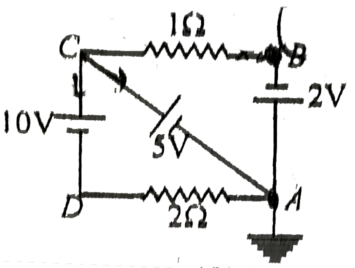
In the circuit shown in the figure, the ratio of VB as VC is
 View Solution
In the circuit shown in the figure, the input voltage Vi is 20V,VBE=0 and VCE=0. The values of IB,IC and β are given by:
 View Solution
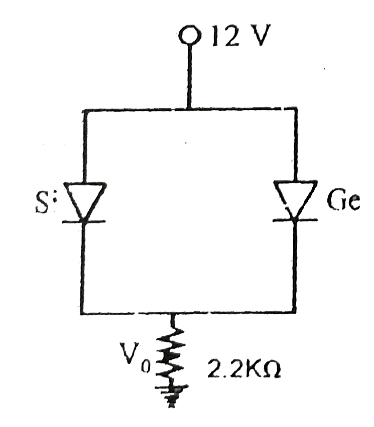
In the circuit shown in figure, Voltage V0 is
 View Solution
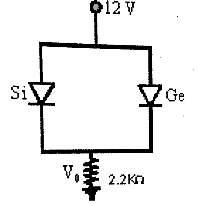
In the circuit shown infigure, voltage V0 is,View Solution


