The part of a circuit shown in the figure consists of two ideal diodes and a few resistors. The equivalent resistance of the circuit between A and B is
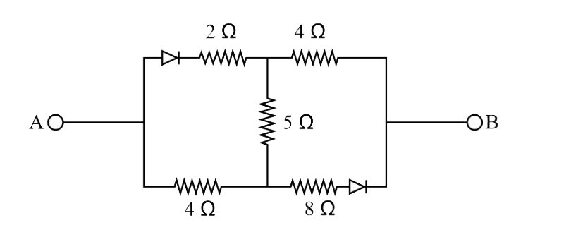
4Ω
13Ω
4Ω or 13Ω
4Ω or zero
The correct Answer is:C
Step by step video & image solution for The part of a circuit shown in the figure consists of two ideal diodes and a few resistors. The equivalent resistance of the circuit between A and B is by Physics experts to help you in doubts & scoring excellent marks in Class 12 exams.
Updated on:21/07/2023Similar Questions
Knowledge Check
The circuit as shown in the figure is equivalent to
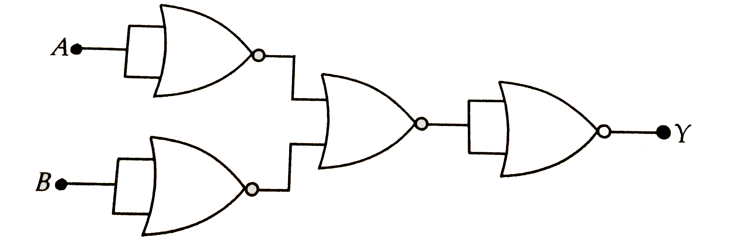 AAND gateBNOT gateCOR gateDNAND gate
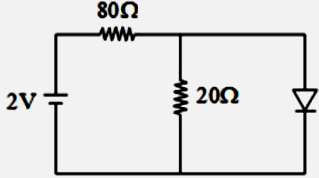
In the circuit shown, the current through the ideal diode is
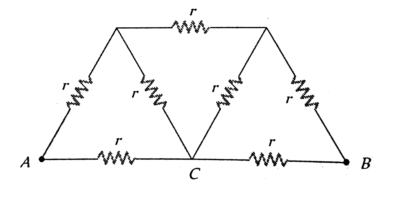
View SolutionIn the circuit shown, the value of each resistance is r , then equivalent resistance of circuit between points A and B will be
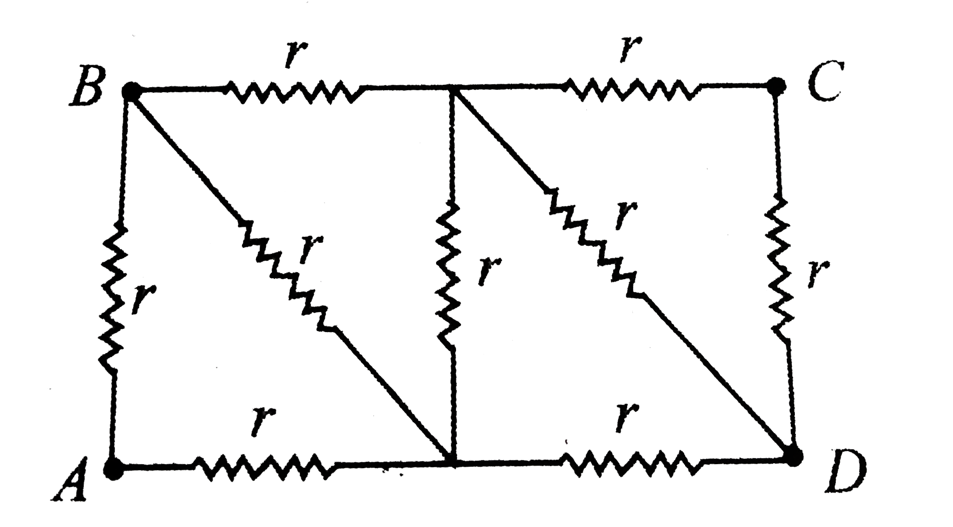
View SolutionFor the circuit shown in fig. the equivalent resistance between A and C is
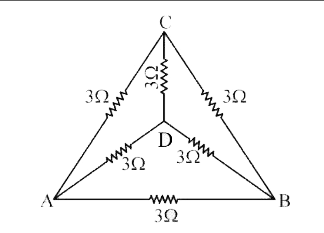
View SolutionThe equivalent resistance between A and B in the given circuit is:
View SolutionThe equivalent capacitance in the circuit shown in figure will be
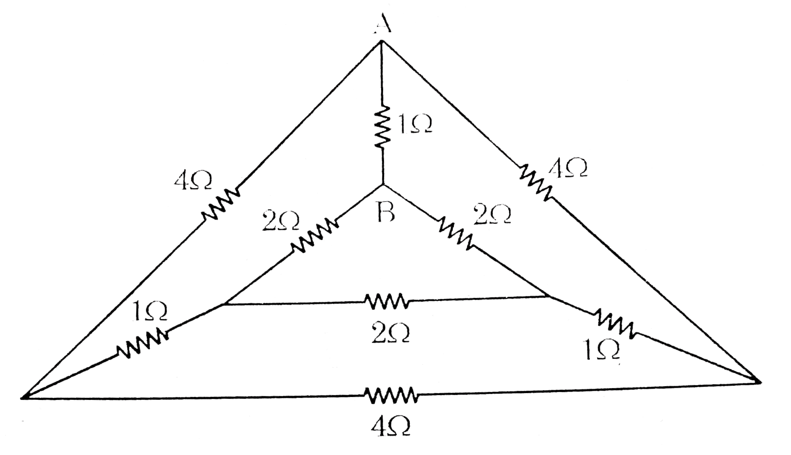
View SolutionConsider the circuit as shown in figure. The equivalent resistance between A and B is
View Solution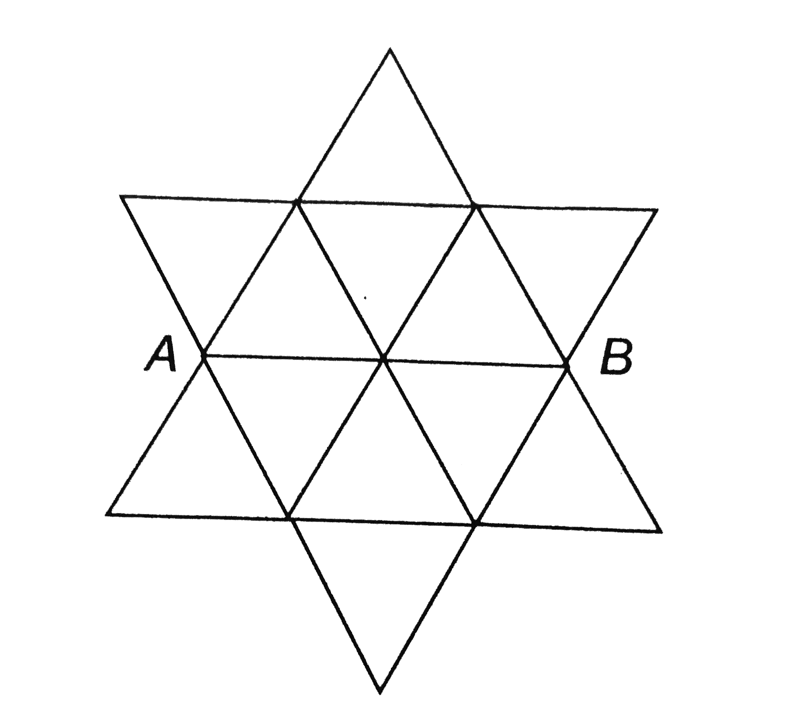
If the resistance of each branch of the circuit shown below is 1Ω , then the equivalent resistance of the circuit between the points A and B is
View Solution

