If A & B are the input as shown in the figure , then output will be


The correct Answer is:A
Step by step video & image solution for If A & B are the input as shown in the figure , then output will be by Physics experts to help you in doubts & scoring excellent marks in Class 12 exams.
Updated on:21/07/2023Similar Questions
(i) Sketch the output waveform from an AND gate for the inputs A and B shown in the figure.
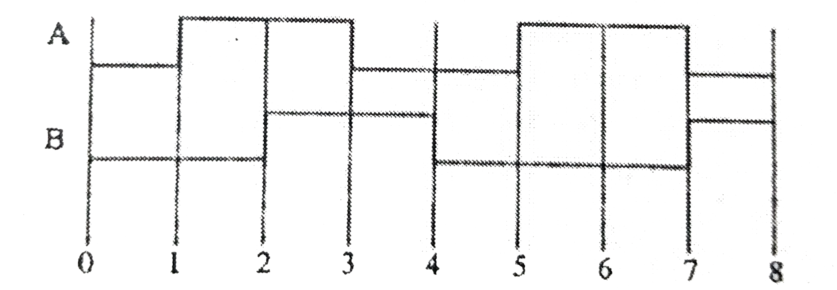
(ii) If the output of the above AND gate is fed to a NOT gate, name the gate of the combination so formed.
View SolutionTo get an output of 1 form the circuit shown in figure the input must be :-
_E01_514_Q01.png)
View SolutionTo get an output 1 from the circuit shown in figure the input must be :

View SolutionA full wave rectifier circuit along with the input and output are shown in the figure. The contribution from the diode D2 is (are)
View SolutionTake the breakdown voltage of the zener diode used in the given circuit as 6V. For the input voltage shown in figure below , the time variation of the output voltage is : (Graphs drawn are schematic and not to scale )

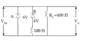
View SolutionTwo Zener diodes (A and B ) having breakdown voltage of 6 V and 4 V respecitvely , are connected as shown in the circuit below . The output voltage V0 variation with input voltage linearly increasing with time is given by :
(Vimput=0Vatt=0) ( figure are qualitative )
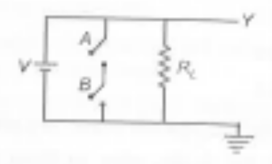
View SolutionThe logic gate realised from the circuit as shown in the figure is (A and B are inputs and Y is output)
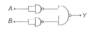
View SolutionOutput Y of the gate shown in figure
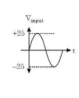
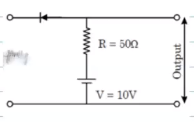
View SolutionAn ideal diode is connected in a circuit with resistance R=50ΩandV=10V. If an AC input signal shown in the figure is given to the circuit, then the maximum and minimum value of output voltage (without load) is
View SolutionWhen the inputs of a two input logic gate are 0 and 0, the output is 1. When the inputs are 1 and 0, the output is zero. The type of logic gate is
View Solution
