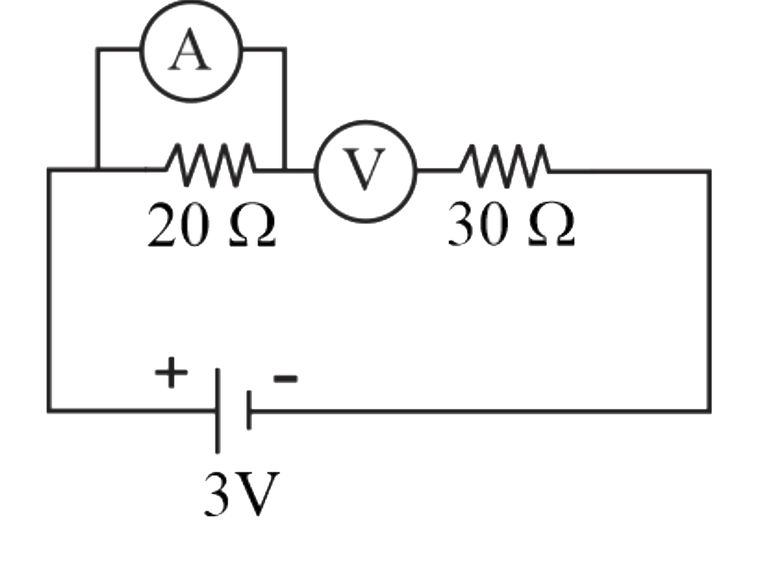
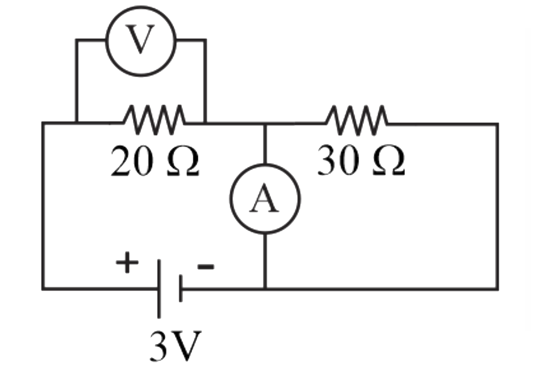
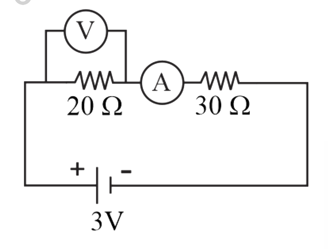
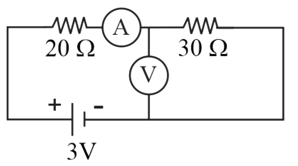
Resistor of resistance are joined in series a battery of emf 3V . It is desired to measure current and voltage across the resistor with the help of an ammeter and a voltmeter. Identify the correct arrangement of ammeter (A) and voltmeter (V) out of four possible arrangement shown in the figure given below.
The correct Answer is:C
To solve the problem of measuring the current and voltage across a 20 Ω resistor in a series circuit with a 30 Ω resistor and a 3V battery, we need to understand the correct arrangement of the ammeter and voltmeter.
1. Understand the Circuit Configuration:
- We have two resistors: 20 Ω and 30 Ω connected in series with a 3V battery.
- In a series circuit, the same current flows through all components.
2. Identify the Function of the Ammeter and Voltmeter:
- The ammeter is used to measure the current flowing through the circuit. It must be connected in series with the component whose current we want to measure.
- The voltmeter is used to measure the voltage across a specific component. It must be connected in parallel with that component.
3. Connect the Ammeter:
- Since we want to measure the current through the 20 Ω resistor, the ammeter should be connected in series with the 20 Ω resistor. This ensures that the current flowing through the resistor is the same as the current measured by the ammeter.
4. Connect the Voltmeter:
- To measure the voltage across the 20 Ω resistor, the voltmeter should be connected in parallel with the 20 Ω resistor. This allows the voltmeter to measure the potential difference across the resistor.
5. Evaluate the Possible Arrangements:
- Out of the four possible arrangements shown in the figure, we need to identify the one where the ammeter is in series with the 20 Ω resistor and the voltmeter is in parallel with the same resistor.
6. Conclusion:
- The correct arrangement will have the ammeter in series with the 20 Ω resistor and the voltmeter in parallel with the 20 Ω resistor. This arrangement allows for accurate measurement of both current and voltage.
Final Answer:
The correct arrangement is where the ammeter (A) is connected in series with the 20 Ω resistor and the voltmeter (V) is connected in parallel with the 20 Ω resistor.
- We have two resistors: 20 Ω and 30 Ω connected in series with a 3V battery.
- In a series circuit, the same current flows through all components.
- The ammeter is used to measure the current flowing through the circuit. It must be connected in series with the component whose current we want to measure.
- The voltmeter is used to measure the voltage across a specific component. It must be connected in parallel with that component.
- Since we want to measure the current through the 20 Ω resistor, the ammeter should be connected in series with the 20 Ω resistor. This ensures that the current flowing through the resistor is the same as the current measured by the ammeter.
- To measure the voltage across the 20 Ω resistor, the voltmeter should be connected in parallel with the 20 Ω resistor. This allows the voltmeter to measure the potential difference across the resistor.
- Out of the four possible arrangements shown in the figure, we need to identify the one where the ammeter is in series with the 20 Ω resistor and the voltmeter is in parallel with the same resistor.
- The correct arrangement will have the ammeter in series with the 20 Ω resistor and the voltmeter in parallel with the 20 Ω resistor. This arrangement allows for accurate measurement of both current and voltage.
The correct arrangement is where the ammeter (A) is connected in series with the 20 Ω resistor and the voltmeter (V) is connected in parallel with the 20 Ω resistor.
Similar Questions
Fig. shows two resistors A of 4Ω and B of 6 Ω joined in series to a battery of e.m.f. 12 V and internal resistance 2 Ω . Calculate :
the p.d. across the resistor B,View SolutionTwo resistor 400Ω and 800Ω connected in series across a 6 V battery . Reading of Voltmeter of 10kΩ across 400Ω resistor is close to :
View Solution
Knowledge Check
- Question 1 - Select One
Three resistors of resistances 3Ω,4Ωand5Ω are combined in parallel. This combination is connected to a battery of emf 12V and negligible internal resistance, current through each resistor in ampere is
A4,3,2.4B8,7,3,4C2,5,1,8D5,5,8,2
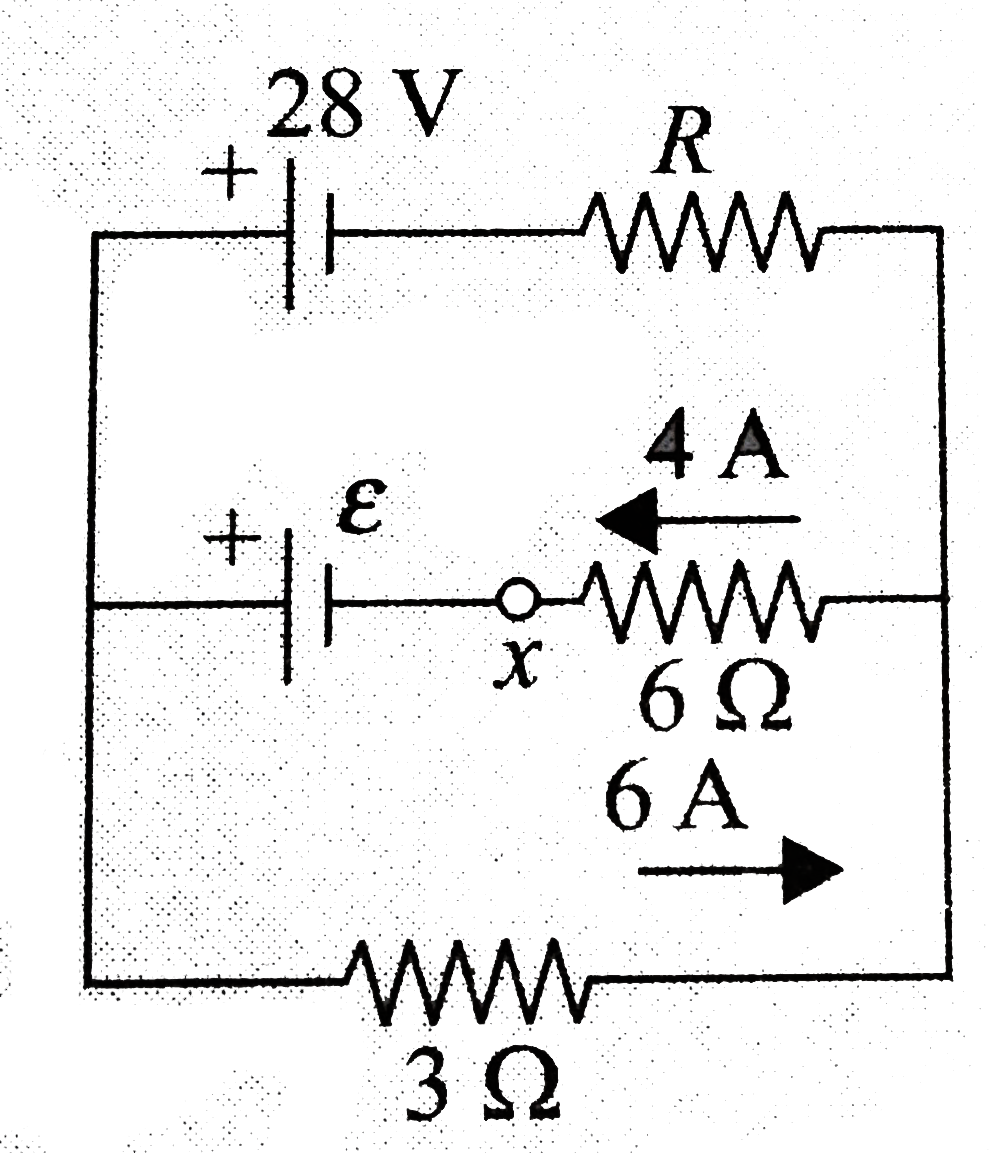
In the circuit shown in fig the voltage across the 6Ω resistor is 12V. What is the emf of the battery and the current thorugh the 6Oemga resistor?
 View Solution
Fig. shows two resistors A of 4Ω and B of 6 Ω joined in series to a battery of e.m.f. 12 V and internal resistance 2 Ω . Calculate :
the terminal voltage of the battery,View SolutionFig. shows two resistors A of 4Ω and B of 6 Ω joined in series to a battery of e.m.f. 12 V and internal resistance 2 Ω . Calculate :

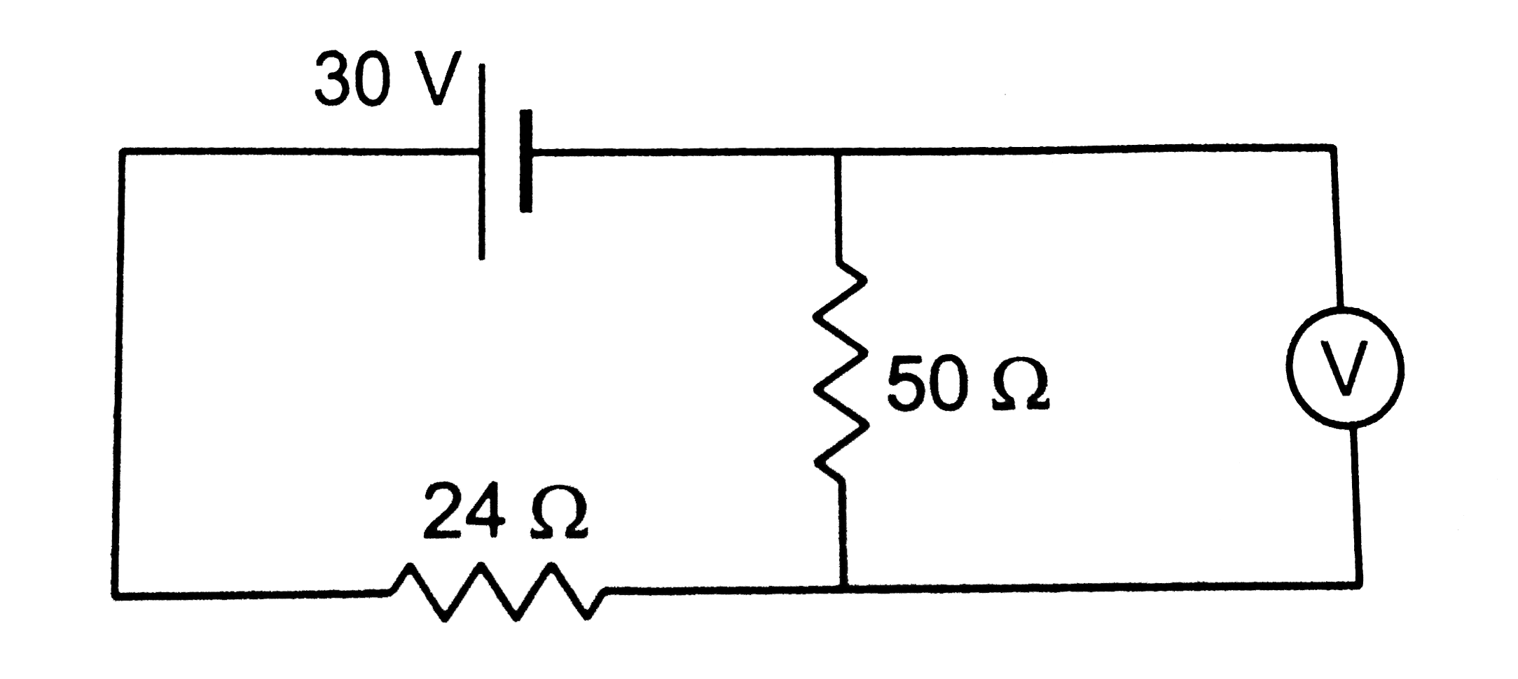
the current in circuit,View SolutionThe voltmeter shown in figure reads 18V across the 50(Ω)resistor. Find the resistance of the voltmeter.
 View Solution
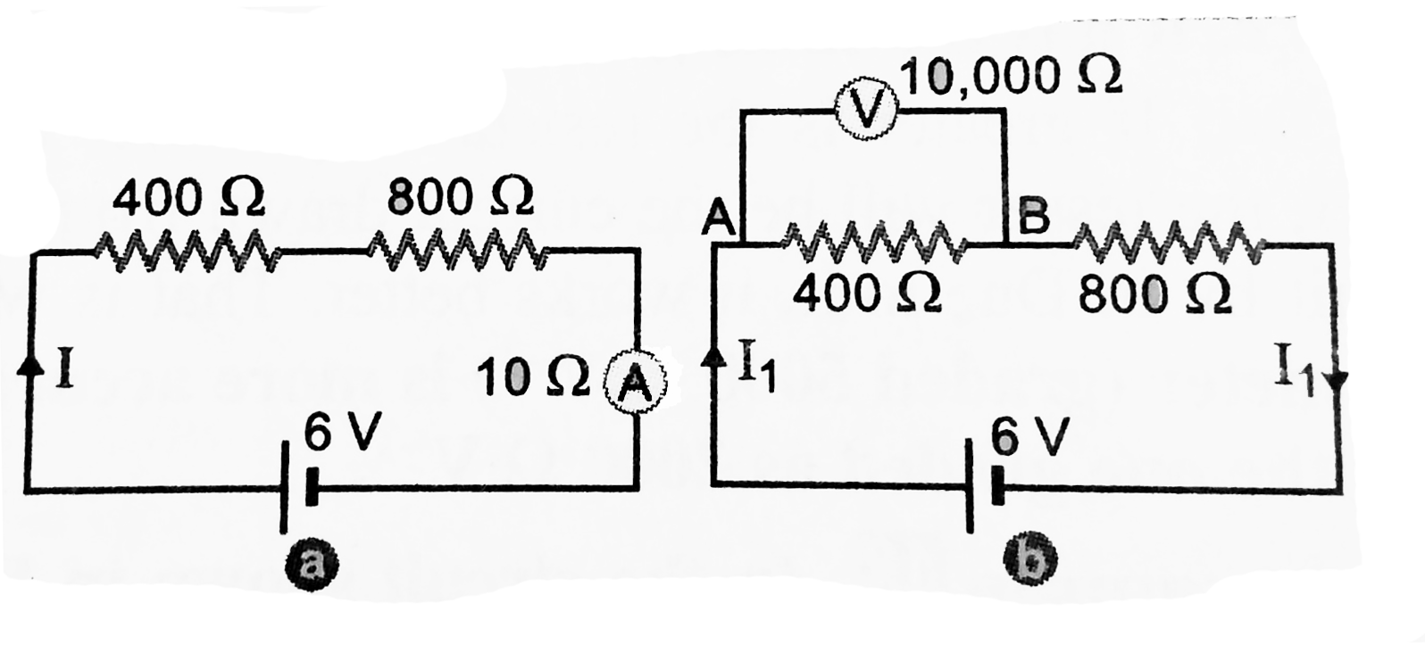
Two resistors 400Ω and 800Ω are connected in series with a 6V battery. It is desired to measure the current in the circuit. An ammeter of 10Ω resistance is used for this purpose figure. What will be the reading in the ammeter? Similarly, if a voltmeter of 10,000Ω resistance is used to measure the potential difference across the 400Ω resistor, what will be the reading in the voltmeter?
 View Solution
Fig. shows two resistors A of 4Ω and B of 6 Ω joined in series to a battery of e.m.f. 12 V and internal resistance 2 Ω . Calculate :
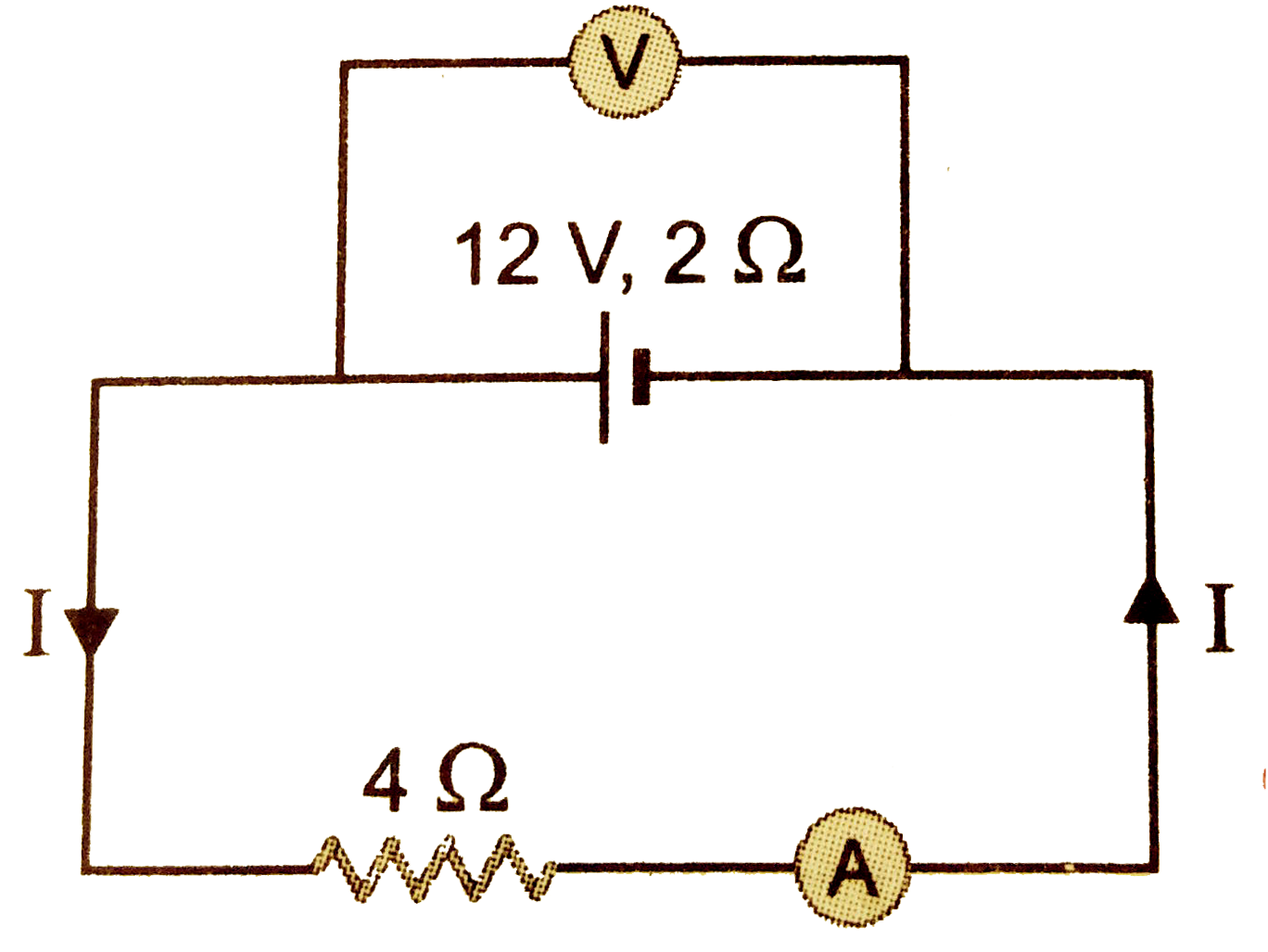
the electrical energy spent in 1 minute in resistor AView SolutionA battery of emf 12V and internal resistance 2Ω is connected two a 4Ω resistor. Show that the a voltmeter when placed across cell and across the resistor in turn given the same reading
 View Solution

