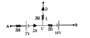
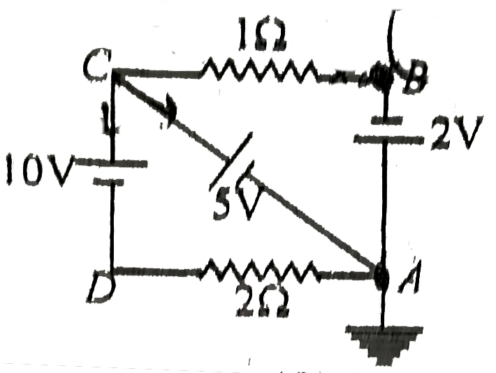
A part of a circuit is shown in figure VR−VC is equal to 12 V. I1 is equal to
A
1A
B
2A
C
3A
D
4A
Video Solution
Text Solution
The correct Answer is:C
If VB−VC=12 then potential drop across 2Ω resistor between B & C is 2V so, current flow from B to C
=22=1A
By junction rule I1=3+1=3A.
|
Topper's Solved these Questions
- CURRENT ELECTRICITYBOOK - PHYSICS WALLAHCHAPTER - CURRENT ELECTRICITYEXERCISE - NEET Past 5 Years Questions
23 Videos
- CURRENT ELECTRICITYBOOK - PHYSICS WALLAHCHAPTER - CURRENT ELECTRICITYEXERCISE - NEET Past 5 Years Questions
23 Videos
- ALTERNATING CURRENT BOOK - PHYSICS WALLAHCHAPTER - ALTERNATING CURRENT EXERCISE - NEET PAST 5 YEARS QUESTIONS
8 Videos
- DUAL NATURE OF RADIATION AND MATTERBOOK - PHYSICS WALLAHCHAPTER - DUAL NATURE OF RADIATION AND MATTEREXERCISE - Neet past 5 years questions
16 Videos
Similar Questions
Knowledge Check
In the circuit shown in figure value of VR is
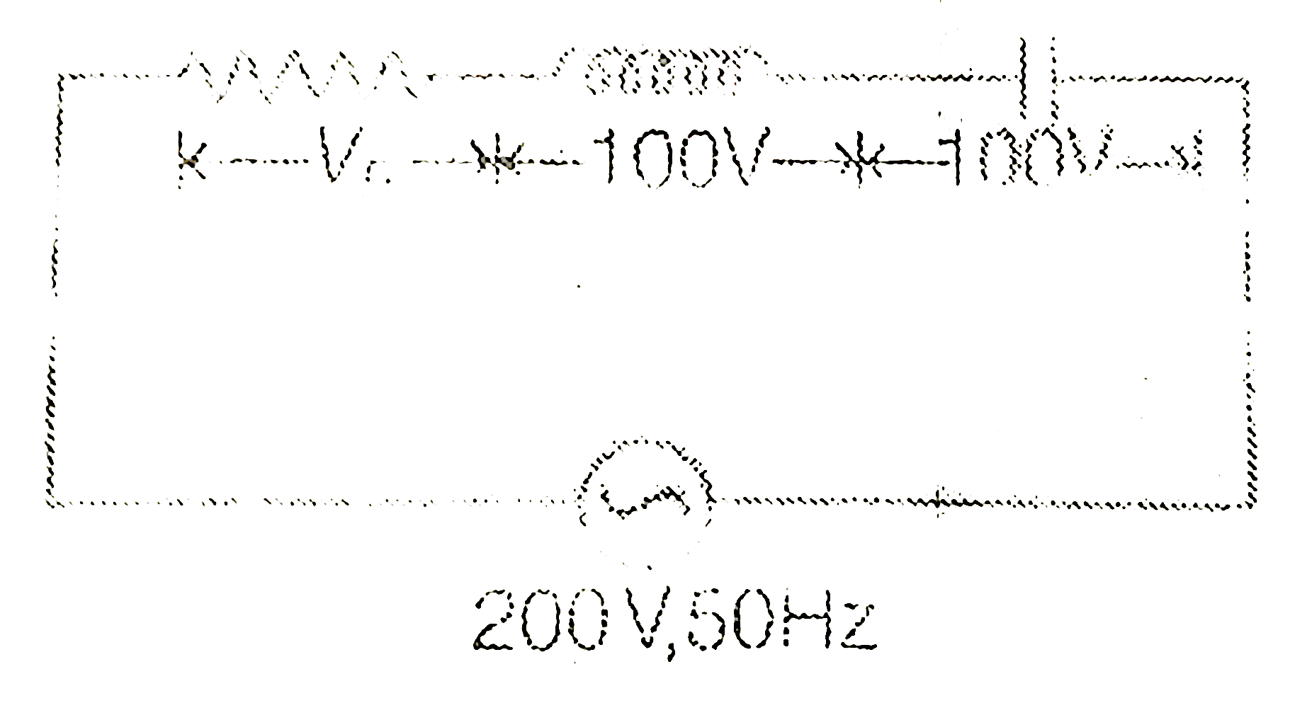 A400VB200VC300VDzero
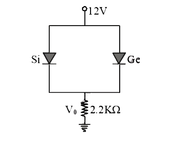
In the circuit shown in figure, Voltage V0 is
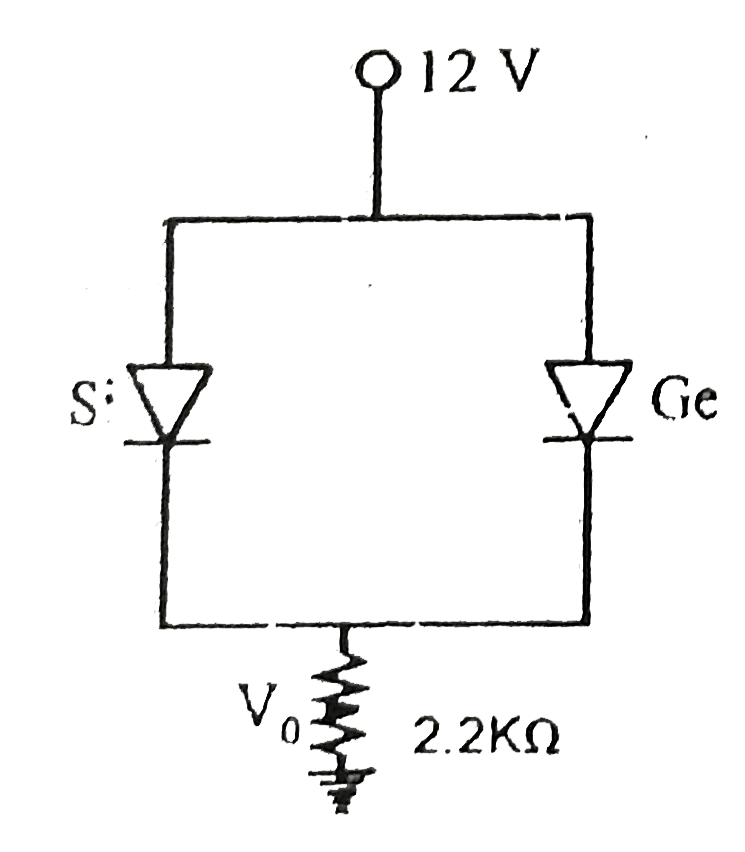 A11.7 voltB11.3 voltC0DNone
In the circuit shown in figure , V must be
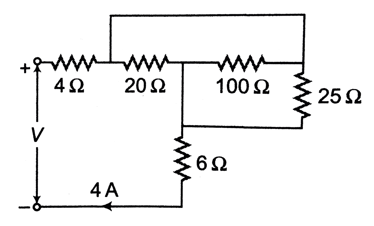 A50VB80VC100VD1290V
In the circuit shown in the figure , V must be
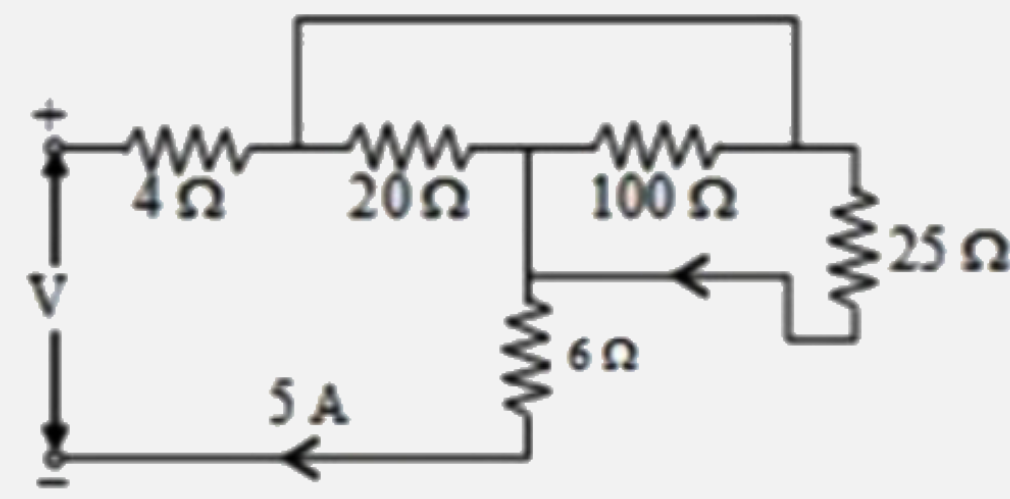
View SolutionIn the circuit shown in the figure , V must be -
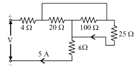
View SolutionA part of a complete circuit is shown in the figure . At some instant the value of current I is 1 A and it is decreasing at a rate of 102As−1 . The value of the potential difference VP−VQ, (in volts) at that instant , is ____________.

View SolutionA circuit is arranged as shown in figure. The output voltage V0 is equal to ____________V.
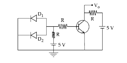
View SolutionIn the circuit shown in the figure, the ratio of VB as VC is
View Solution


