The curves (a), (b), (c) and (d) show the variation between the applied potential difference (V) and the photoelectric current (i), at two different intensities of light (I1>I2). In which figure is the correct variation shown


The correct Answer is:B
I1>I2 (given)⇒i1>i2(∵iαI)
and stopping potential does not depend upon intensity . So its value will be same (V0).
Similar Questions
The curves (a),(b),(c) and (d) show the variation between the applied potential difference (V) and the photoelectric current (i) , at two different intensities of light (I1>I2). In which figure is the correct variation shown ?
View SolutionFor a metallic wire, the ratio Vi ( V= applied potential difference and i= current flowing ) is
View Solution
Knowledge Check
The curves (a),(b),(c) and (d) show the variation between the applied potential difference (V) and the photoelectric current (i) , at two different intensities of light (I1>I2). In which figure is the correct variation shown ?
A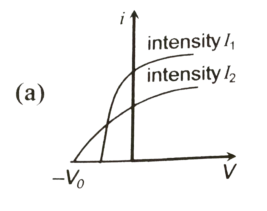 B
B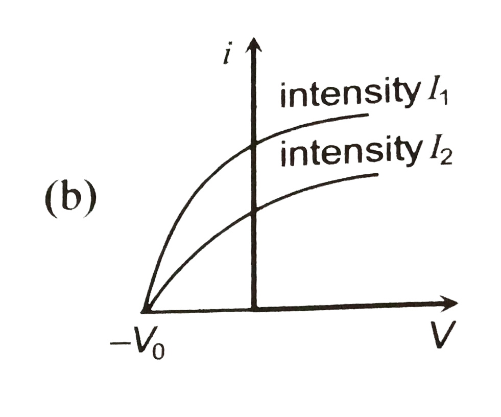 C
C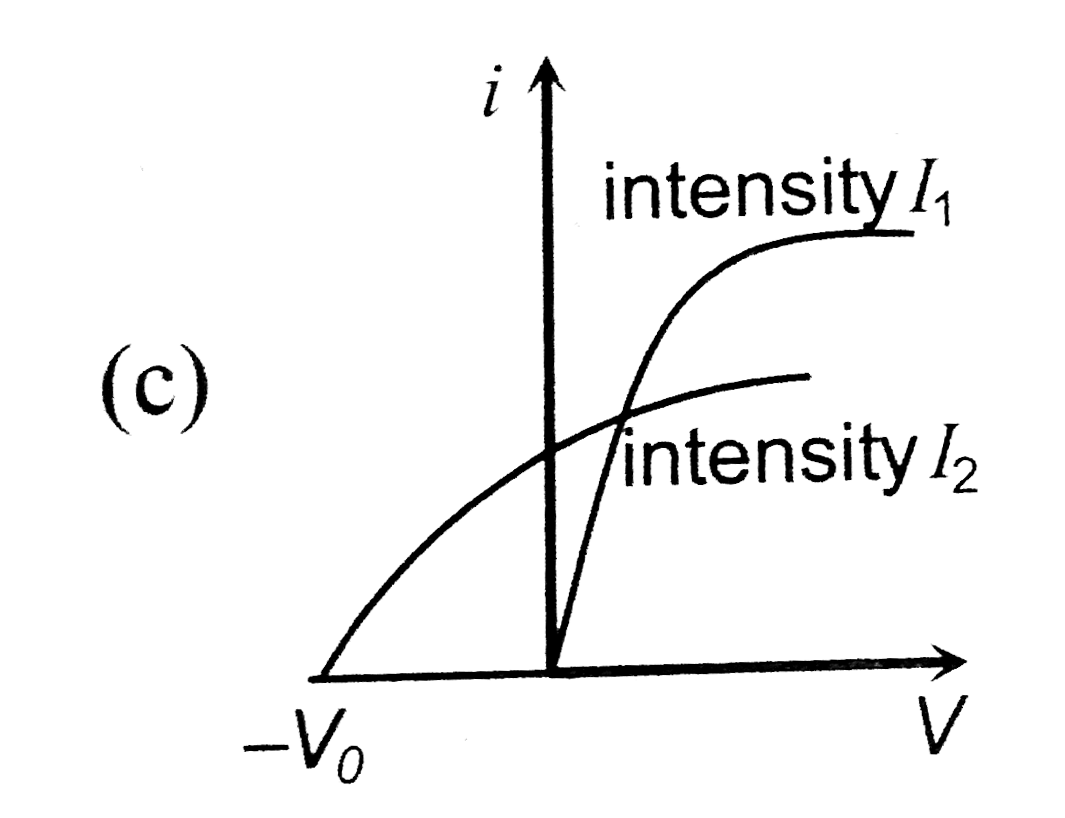 D
D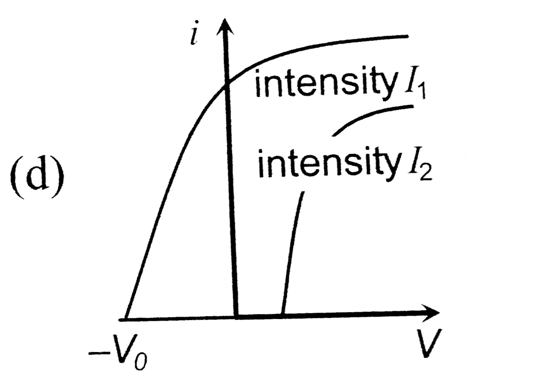
The curve between current (i) and potential difference (V) for a photo cell will be
A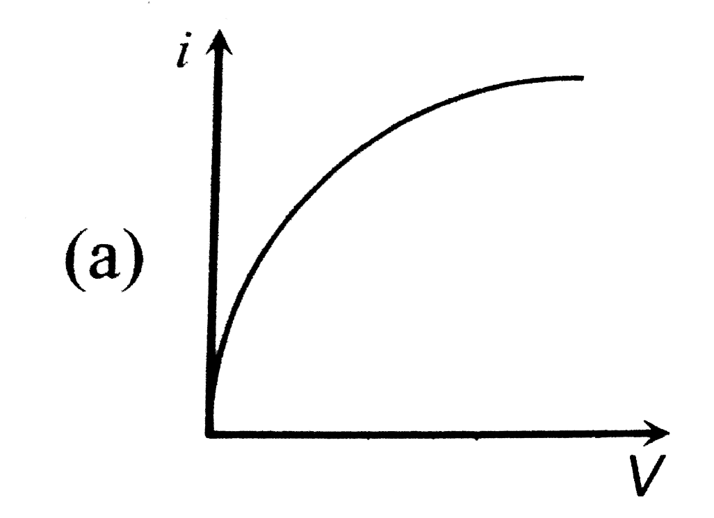 B
B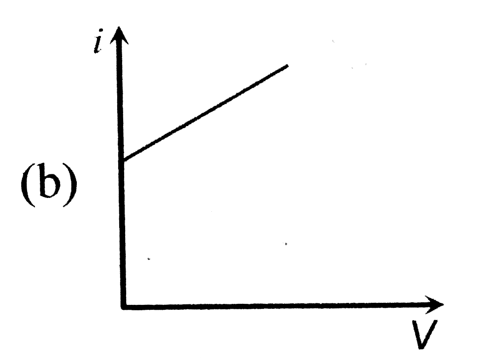 C
C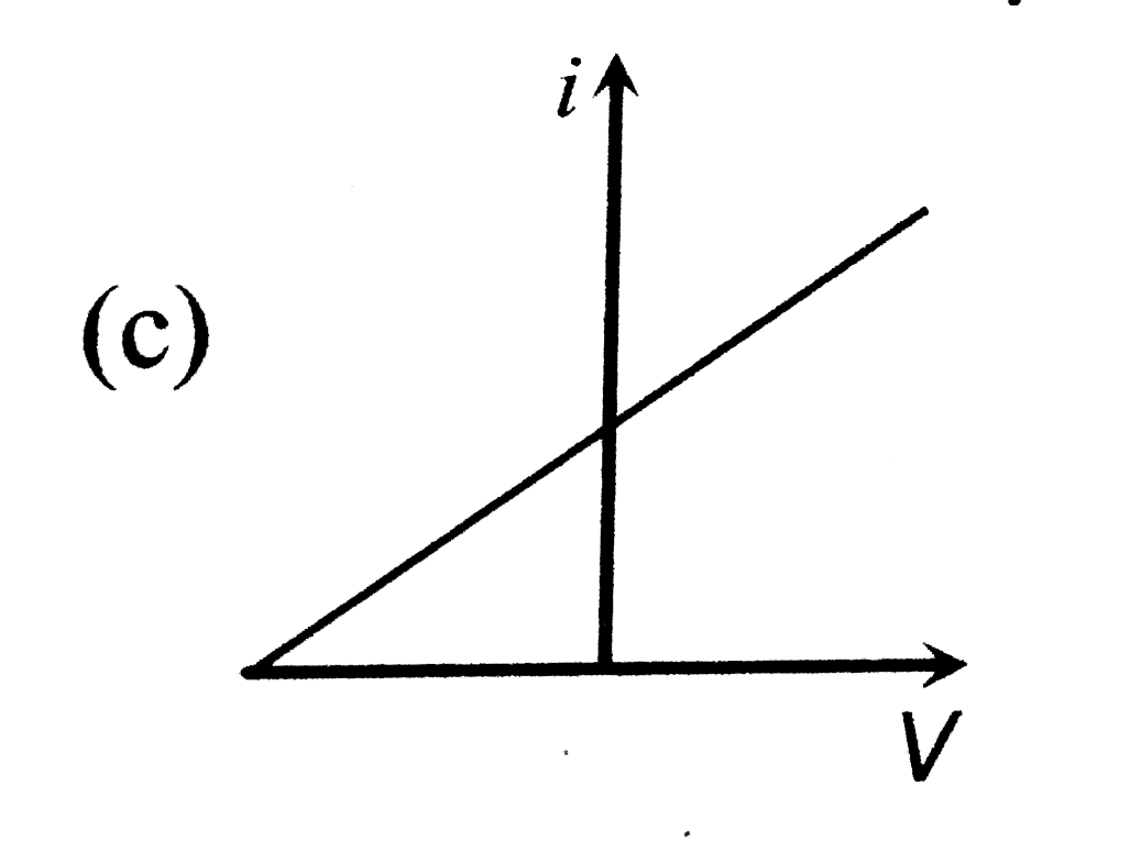 D
D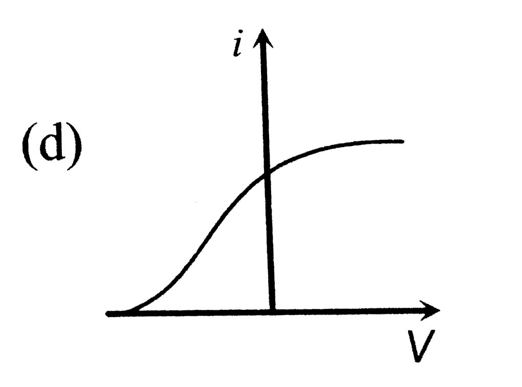
For a metallic wire, the ratio Vi(V=applied potential difference and i= current flowing)is
Aindependent of temperatureBincreases as the temperature risesCdecreases as the temperature risesDincreases or decreases as temperature rises depending upon the metal
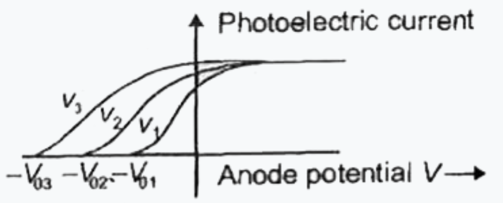
In photoelectric effect , the curve between photoelectric current and anode potential V (for different frequencies ) is shown in figure , then
View SolutionFor a metallic wire, the ratio Vi(V=applied potential difference and i= current flowing)is
View SolutionFor a metallic wire, the ratio Vi ( V= applied potential difference and i= current flowing ) is
View SolutionThe relation between potential difference (V) and current (I) was discovered by:
A) Pascal
B) Tesla
C) Newton
D) Ohm
View SolutionIn photoelectric effect , the curve between photoelectric current and anode potential V (for different frequencies ) is shown in figure , then

View Solution
