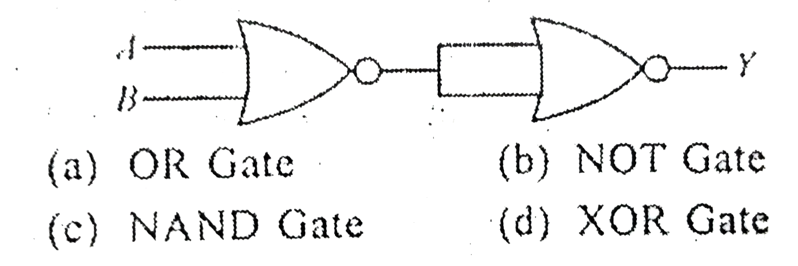
The logic gate represented in following figure is
OR Gate
NOT Gate
NAND Gate
XOR Gate
The correct Answer is:A
(##AIIMSENTSP10_E01003_S01.png width=80%><br> Y' = bar ( A + B ) = + bar A * bar B <br>and Y = bar ( Y' ) = bar ( bar A * bar B ) = bar bar A + bar bar B = A + B
This is the boolean expression for the OR gate.
Similar Questions
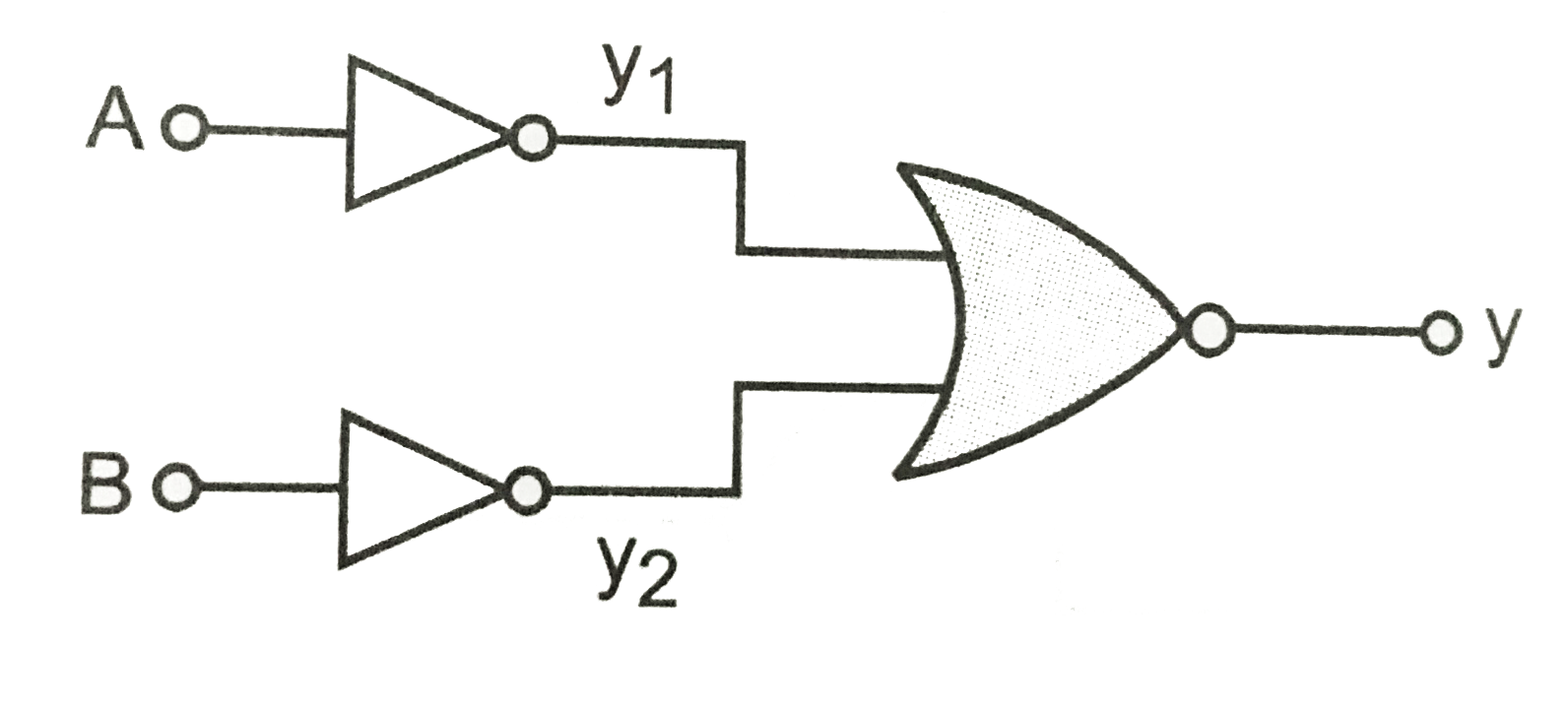
Which logic gate is represented by the following combination of logic gates
View Solution(a) In the figure given below the input waveform is converted into the output waveform by a device 'X'. Name the device and draw its circuit diagram.

(b) Identify the logic gate represented by the circuit as shown and write its truth table.

View Solution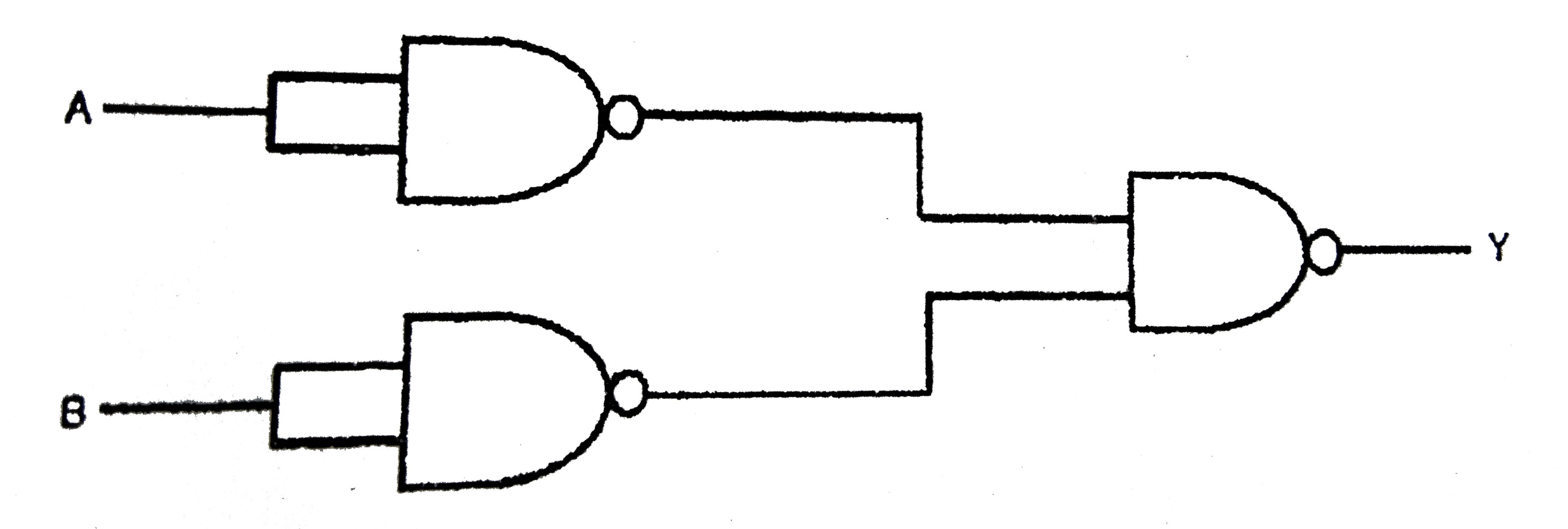
Draw the truth table for the logic gate arrangement shown in the figure.
View SolutionThe logic gate given below represents a

View SolutionAn X-OR gate has following truth table:
It is represented by following logic relation
y=¯¯¯A.B+A.¯¯¯B
Build this gate using AND, OR and NOT gates.
∣∣ ∣ ∣ ∣ ∣ ∣∣ABY000011101110∣∣ ∣ ∣ ∣ ∣ ∣∣
View SolutionYou are given two circuits as shown in following figure. The logic operation carried out by the two circuit are respectively :-
_E01_415_Q01.png)
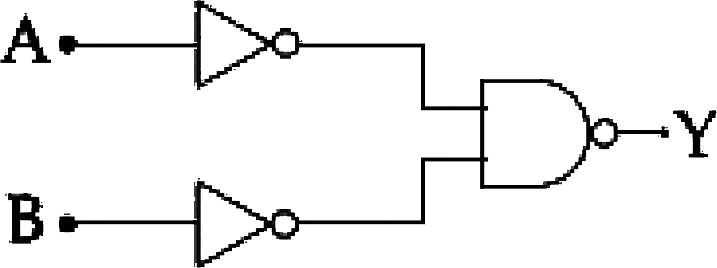
View SolutionThe logic gate equivalent to the given logic circuit is :
View SolutionWhich of the following defects is represented in the given figure ?
View SolutionWhat do the following figures represent?

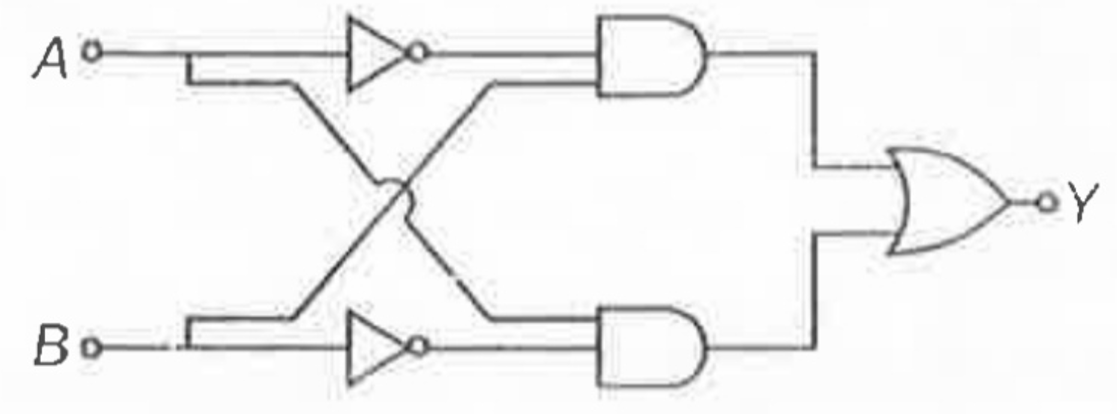
View SolutionThe logic circuit (figure) represents which logic gate?
View Solution
