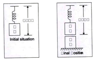
Consider a magnet which is hung by the hook of a spring as shown in figure. Then what could be the possible option from the following to attain the final position shown in figure.
A
X, A are North Pole and Y, B are South Pole
B
X, Bare North Pole and Y, A are South Pole
C
X, Bare South Pole and Y, A are North Pole
D
X, A are South Pole and Y, B are South Pole
Text Solution
The correct Answer is:A
In the second picture it is observed that the spring length increased. This shows that the .Y. part is attracting towards .A., i.e., .Y. and .A.are oppossite poles.
|
Topper's Solved these Questions
- THE MAGICAL MAGNETISM BOOK - PEARSON IIT JEE FOUNDATIONCHAPTER - THE MAGICAL MAGNETISM EXERCISE - ASSESSMENT TEST (Test 1)
11 Videos
- THE MAGICAL MAGNETISM BOOK - PEARSON IIT JEE FOUNDATIONCHAPTER - THE MAGICAL MAGNETISM EXERCISE - TEST YOUR CONCEPTS(Very Short Answer Type Questions)
13 Videos
- THE MACHANISM OF MACHINESBOOK - PEARSON IIT JEE FOUNDATIONCHAPTER - THE MACHANISM OF MACHINESEXERCISE - CROSSWORD
1 Videos
- THE MECHANISM OF MACHINES BOOK - PEARSON IIT JEE FOUNDATIONCHAPTER - THE MECHANISM OF MACHINES EXERCISE - Crossword
1 Videos
Similar Questions
Knowledge Check
Consider a magnet which is hung to the hook of a spring as shown in figure. Then what could be the possible option from the following?
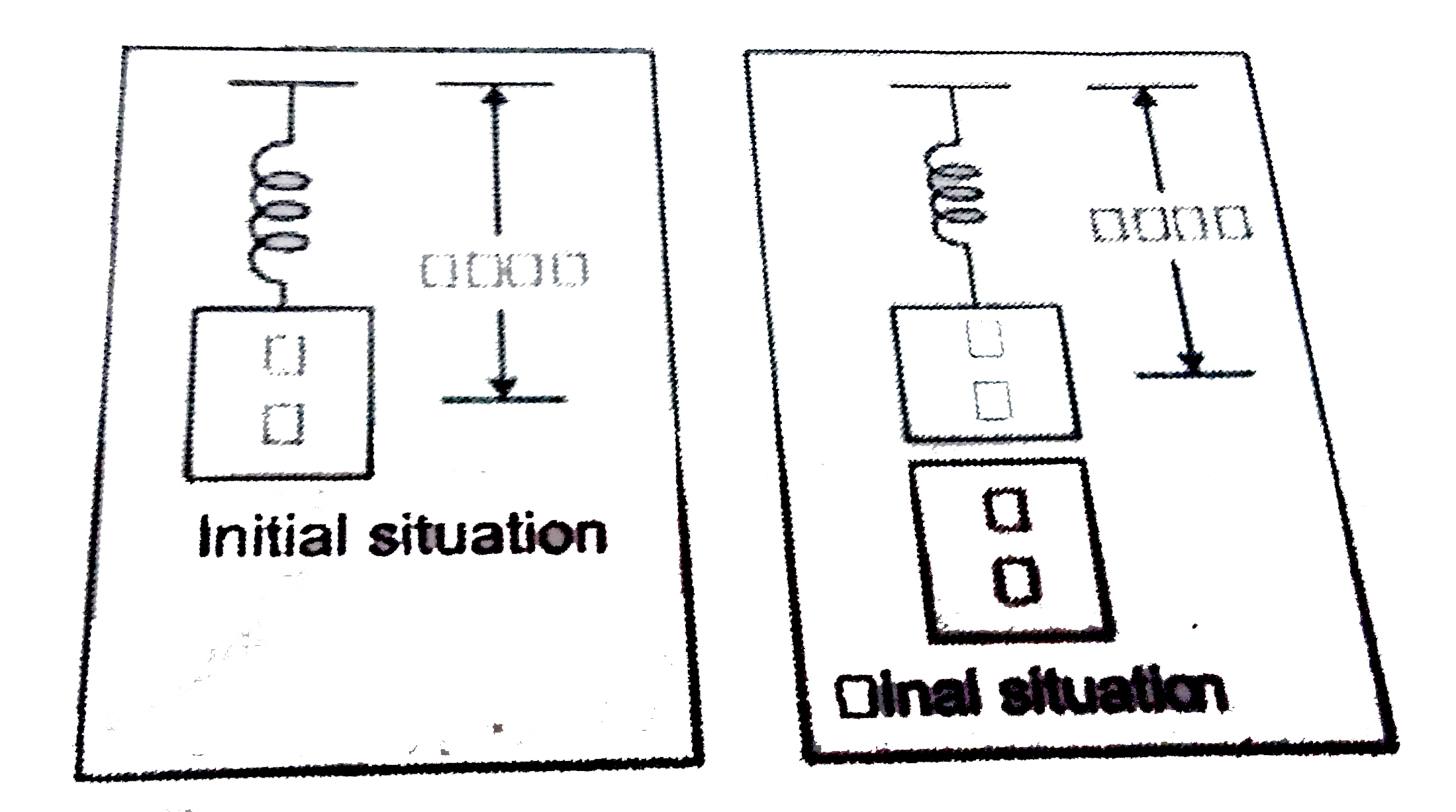
(i) X,A are North Pole and Y,B are south Pole
(ii) X, B are North Pole and Y,A are South Pole
(iii) A,B are South Pole and X,Y are North Pole
(iv) X,A are South Pole and Y,B are North Pole.AOnly(ii)BOnly (i)CBoth (i) and (ii)DBoth (ii) and (iii)Consider a magnet which is hung to the hook of a spring as shown in figure. Then what could be the possible option from the following?

(i) X,A are North Pole and Y,B are south Pole
(ii) X, B are North Pole and Y,A are South Pole
(iii) A,B are South Pole and X,Y are North Pole
(iv) X,A are South Pole and Y,B are North Pole.AOnly (ii)BOnly (i)CBoth (i) and (ii)DBoth (ii) and (iii)What will be the force constant of the spring system shown in figure?
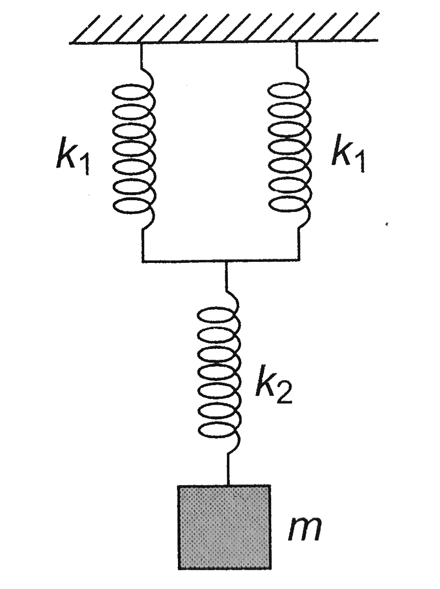 A[1k1+1k2]B[12k1+1k2]−1C[1k1+1k2]−1D[12k1+1k2]
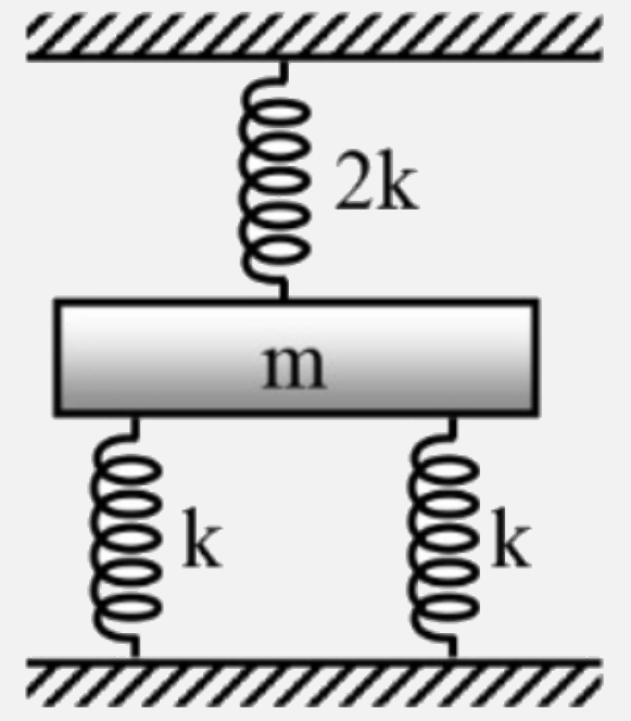
What is the spring constant for the combination of shown shown in figure ?
View SolutionFor the circuit shown in figure, select the correct statements from the following options :
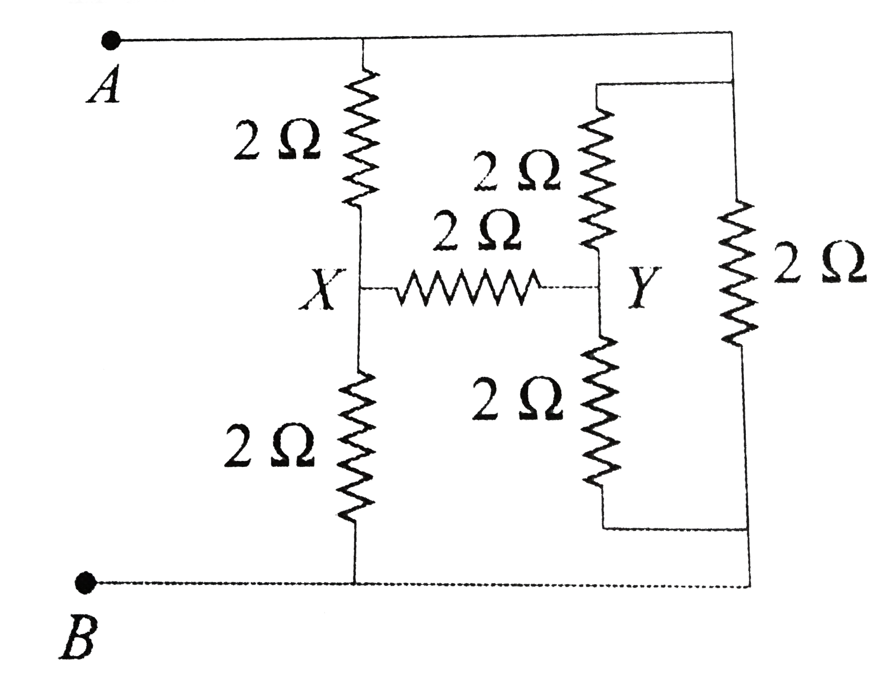 .
.
View SolutionFor the circuit shown in figure, select the correct statements from the following options :
 .
.
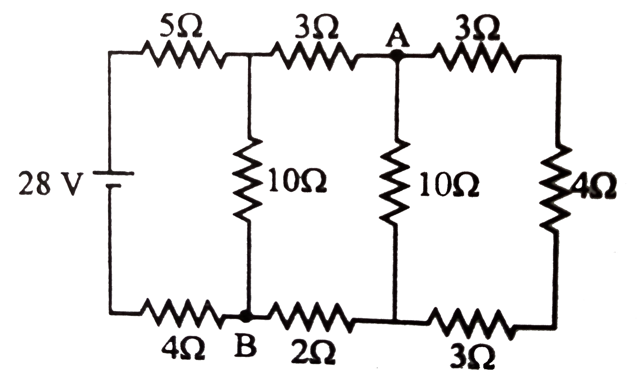
View SolutionConsider the circuit shown in the figure
View SolutionFor the circuit shown in figure, select the correct statements from the following options :
 .
.
View Solution

