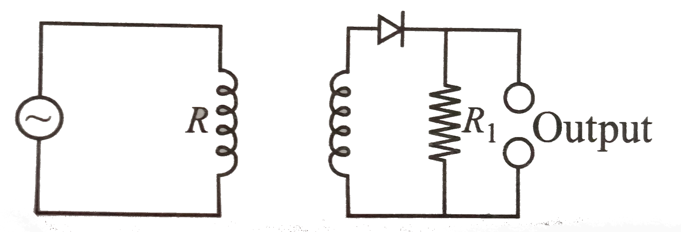
A sinusoidal voltage of amplitude 25 volts and frequency 50 Hz is applied to a half wave rectifier using PN diode. No filter is used and the load resistor is 1000Ω. The forward resistance Rf ideal diode is 10Ω. Calculate.
(i) Peak, average and rms values of load current
(ii) d.c power output
(ii) a.c power input
(iv) % Rectifier efficiency
(v) Ripple factor.
To solve the problem step by step, we will calculate the peak, average, and RMS values of the load current, followed by the DC power output, AC power input, percentage rectifier efficiency, and the ripple factor.
Step 1: Calculate the Peak Current (I_peak)
The peak current (I_peak) can be calculated using the formula:
Ipeak=VmReq
Where:
- Vm=25V (peak voltage)
- Req=Rf+RL=10Ω+1000Ω=1010Ω
Now substituting the values:
Ipeak=251010≈0.02475A=24.75mA
Step 2: Calculate the Average Current (I_avg)
The average current for a half-wave rectifier is given by:
Iavg=Ipeakπ
Substituting the value of Ipeak:
Iavg=24.75mAπ≈24.753.14≈7.88mA
Step 3: Calculate the RMS Current (I_rms)
The RMS current for a half-wave rectifier is given by:
Irms=Ipeak2
Substituting the value of Ipeak:
Irms=24.75mA2≈12.375mA
Step 4: Calculate the DC Power Output (P_dc)
The DC power output can be calculated using the formula:
Pdc=I2avg×RL
Substituting the values:
Pdc=(7.88×10⁻³)2×1000≈0.063W=63mW
Step 5: Calculate the AC Power Input (P_ac)
The AC power input can be calculated using the formula:
Pac=I2rms×Req
Substituting the values:
Pac=(12.375×10⁻³)2×10¹⁰≈0.155W=155mW
Step 6: Calculate the Rectifier Efficiency (% η)
The rectifier efficiency is given by:
η=PdcPac×100
Substituting the values:
η=63mW155mW×100≈40.65%
Step 7: Calculate the Ripple Factor (r)
The ripple factor for a half-wave rectifier is given by:
r=√(IrmsIavg)2−1
Substituting the values:
r=√(12.375×10−37.88×10−3)2−1≈√(1.57)2−1≈1.21
Summary of Results
1. Peak Current (I_peak): 24.75 mA
2. Average Current (I_avg): 7.88 mA
3. RMS Current (I_rms): 12.38 mA
4. DC Power Output (P_dc): 63 mW
5. AC Power Input (P_ac): 155 mW
6. Rectifier Efficiency (% η): 40.65%
7. Ripple Factor (r): 1.21
The peak current (I_peak) can be calculated using the formula:
Ipeak=VmReq
Where:
- Vm=25V (peak voltage)
- Req=Rf+RL=10Ω+1000Ω=1010Ω
Ipeak=251010≈0.02475A=24.75mA
The average current for a half-wave rectifier is given by:
Iavg=Ipeakπ
Iavg=24.75mAπ≈24.753.14≈7.88mA
The RMS current for a half-wave rectifier is given by:
Irms=Ipeak2
Irms=24.75mA2≈12.375mA
The DC power output can be calculated using the formula:
Pdc=I2avg×RL
Pdc=(7.88×10⁻³)2×1000≈0.063W=63mW
The AC power input can be calculated using the formula:
Pac=I2rms×Req
Pac=(12.375×10⁻³)2×10¹⁰≈0.155W=155mW
The rectifier efficiency is given by:
η=PdcPac×100
η=63mW155mW×100≈40.65%
The ripple factor for a half-wave rectifier is given by:
r=√(IrmsIavg)2−1
r=√(12.375×10−37.88×10−3)2−1≈√(1.57)2−1≈1.21
1. Peak Current (I_peak): 24.75 mA
2. Average Current (I_avg): 7.88 mA
3. RMS Current (I_rms): 12.38 mA
4. DC Power Output (P_dc): 63 mW
5. AC Power Input (P_ac): 155 mW
6. Rectifier Efficiency (% η): 40.65%
7. Ripple Factor (r): 1.21
Topper's Solved these Questions
- BOOK - ALLENCHAPTER - WAVES AND OSCILLATIONSEXERCISE - Part-1(Exercise-01)53videos
WAVES AND OSCILLATIONS
- BOOK - ALLENCHAPTER - WAVES AND OSCILLATIONSEXERCISE - Part-1(Exercise-02)19videos
WAVES AND OSCILLATIONS
- BOOK - ALLENCHAPTER - WAVES AND OSCILLATIONSEXERCISE - Part-2(Example)15videos
WAVES AND OSCILLATIONS
- BOOK - ALLENCHAPTER - SEMICONDUCTORSEXERCISE - Part-3(Exercise-4)51videos
SEMICONDUCTORS
Similar Questions
A fullwave P.N diode rectifier used load resistor of 1500Ω. No filter is used. Assume each diode to have idealized characteristic with Rf=10Ω and Rr=ac. Since wave voltage applied to each diode has amplitude of 30 volts and frequency 50 Hz. Calculate.
(i) Peak, d.c rms load current
(ii) d.c power output
(iii) A.C power input
(iv) Rectifier efficiency.View SolutionThe halfwave rectifier supplies power to be 1kΩ. The input supply voltage is 220 V neglecting forward resistance of the diode, calculate
(i) Vdc
(ii) Iac and
(iii) Ripple voltage (rms value)View Solution
Knowledge Check
- Question 1 - Select One
A sinusoidal voltage of peak value 293 V and frequency 50 Hz is applie to a series LCR circuit in which R=6Ω,L=25mH and C=750μF. The impedance of the circuit is
A7.0ΩB8.9ΩC9.9ΩD10.0Ω - Question 2 - Select One
A sinusoidal voltage of rms value 220 V is applied to a diode and a resistor R in the circuit shown in figure so that half wave rectification occurs. If the diode is ideal, what is the rms voltage across R1?
 A55√2 VB110 VC110√2 VD220√2 V
A sinusoidal voltage of frequency 60 Hz and peak value 150 V is applied to a series L-R circuit, where R=20Ω and L=40 mH.
a) Compute T, omega, XLView SolutionIn the circuit of the figure, treat diode as ideal, current in the 4Ω resistor is
 View Solution
A silicon diode has a threshold voltage of 0.7 V. If an input voltage given by 2sin(πt) is supplied to a half wave rectifier circuit using this diode, the rectified output has a peak value of
View SolutionIn input in a full - wave rectifier is e=50sin(314t) volt, diode resistance is 100Ω and load resistance is 1kΩ then, pulse frequency of output voltage is
View SolutionFor half wave rectifier if load resistance Rd is 2kΩ and P-N junction resistance RL is 2kΩ determine rectification efficiency.
View SolutionA sinusoidal voltage of peak value 200 volts is connected to a diode and resistor R in the circuit shown so that half wave rectification occurs. If the forward resistance of the diode is negligible compared to R the rms voltage (in volt) across R is approximately
 View Solution

