A silicon diode has a threshold voltage of 0.7 V. If an input voltage given by 2sin(πt) is supplied to a half wave rectifier circuit using this diode, the rectified output has a peak value of
2 V
1.4 V
1.3 V
0.7 V
The correct Answer is:C
To solve the problem, we will follow these steps:
Step 1: Identify the given values
- The threshold voltage of the silicon diode (Vs) is given as 0.7 V.
- The input voltage (Vi) is given by the equation Vi=2sin(πt).
Step 2: Determine the peak value of the input voltage
The input voltage can be expressed in the standard form V=V0sin(ωt), where V0 is the peak voltage. From the equation Vi=2sin(πt), we can see that:
- The peak value V0=2 V.
Step 3: Calculate the rectified output voltage
In a half-wave rectifier circuit using a silicon diode, the output voltage is only present when the input voltage exceeds the threshold voltage. Therefore, the peak output voltage (Vout) can be calculated as:
- Vout=V0−Vs
- Substituting the values: Vout=2V−0.7V=1.3V.
Step 4: Conclusion
The peak value of the rectified output voltage is 1.3V.
Final Answer
The rectified output has a peak value of 1.3 V.
---
- The threshold voltage of the silicon diode (Vs) is given as 0.7 V.
- The input voltage (Vi) is given by the equation Vi=2sin(πt).
The input voltage can be expressed in the standard form V=V0sin(ωt), where V0 is the peak voltage. From the equation Vi=2sin(πt), we can see that:
- The peak value V0=2 V.
In a half-wave rectifier circuit using a silicon diode, the output voltage is only present when the input voltage exceeds the threshold voltage. Therefore, the peak output voltage (Vout) can be calculated as:
- Vout=V0−Vs
- Substituting the values: Vout=2V−0.7V=1.3V.
The peak value of the rectified output voltage is 1.3V.
The rectified output has a peak value of 1.3 V.
Similar Questions
Draw the circuit diagram of a half - wave rectifier using a p-n junction diode.
View SolutionA sinusoidal voltage of amplitude 25 volts and frequency 50 Hz is applied to a half wave rectifier using PN diode. No filter is used and the load resistor is 1000Ω. The forward resistance Rf ideal diode is 10Ω. Calculate.
(i) Peak, average and rms values of load current
(ii) d.c power output
(ii) a.c power input
(iv) % Rectifier efficiency
(v) Ripple factor.
View Solution
Knowledge Check
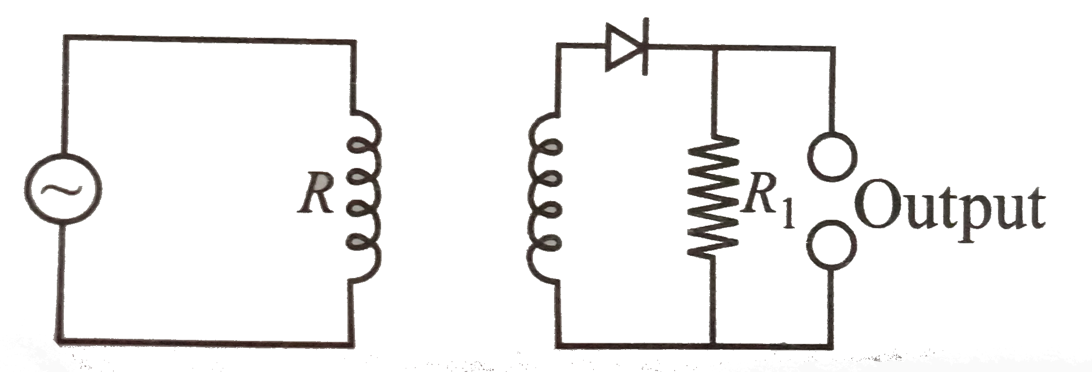
A sinusoidal voltage of rms value 220 V is applied to a diode and a resistor R in the circuit shown in figure so that half wave rectification occurs. If the diode is ideal, what is the rms voltage across R1?
 A55√2 VB110 VC110√2 VD220√2 V
The amplifiers X,Y and Z are connected in series. If the voltage gains of X,Y and Z are 10,20 and 30, respectively and the input signal is 1mV peak value, then what is the output signal voltage (peak value)
(i) if dc supply voltage is 10V ?
(ii) if dc supply voltage is 5V?A4VB5 VC6 VD7 V
The amplifiers X,Y and Z are connected in series. If the voltage gains of X,Y and Z are 10,20 and 30, respectively and the input signal is 1mV peak value, then what is the output signal voltage (peak value)
(i) if dc supply voltage is 10V ?
(ii) if dc supply voltage is 5V?
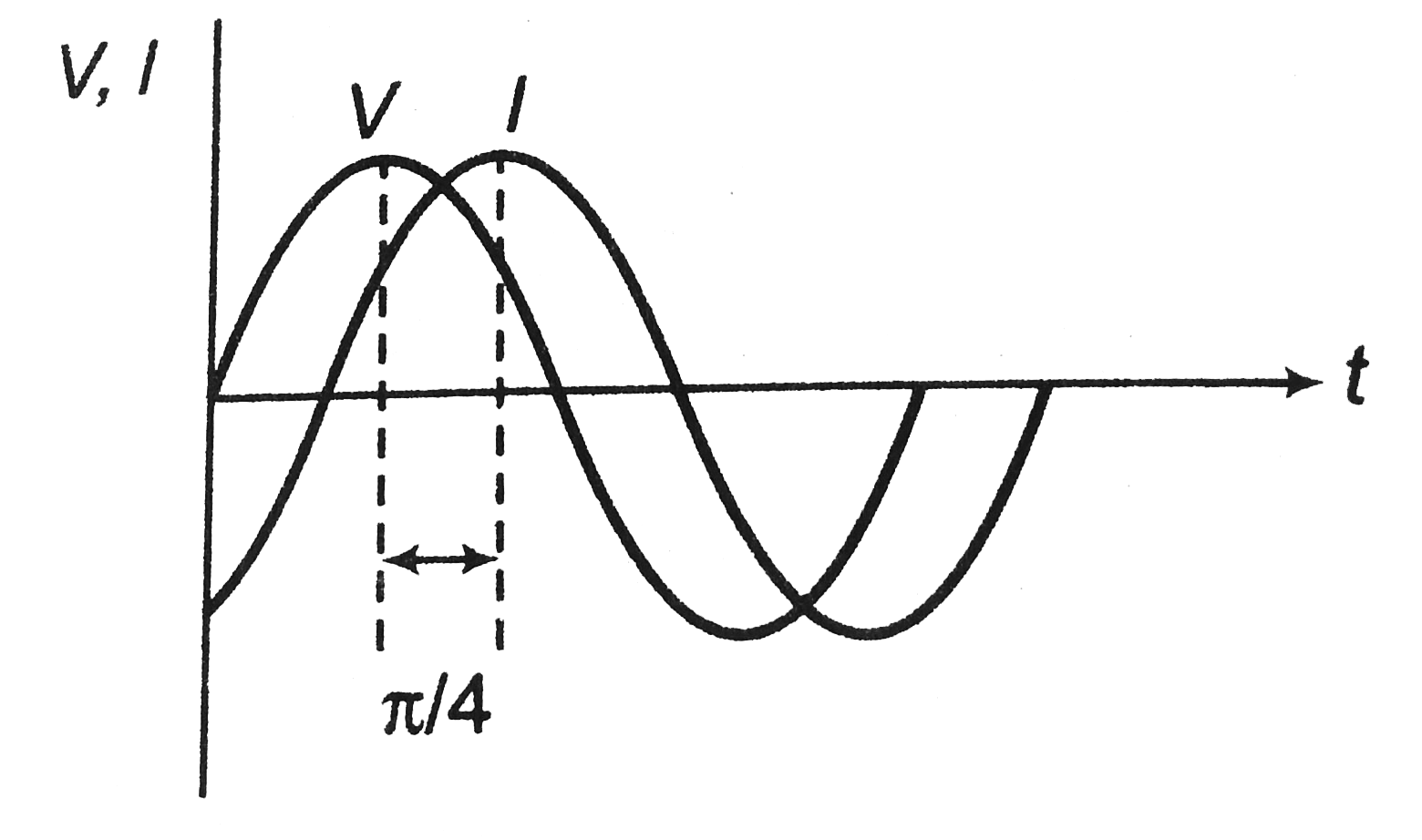
View SolutionAn Ac voltage V=V0sin100t is applied to the circuit, the phase difference between current and voltage is found to be π4, then
 .
.
View SolutionAn Ac voltage V=V0sin100t is applied to the circuit, the phase difference between current and voltage is found to be π4, then
 .
.
View SolutionAn alternating voltage v(t)=220sin100πt volt is applied to a pureluy resistive load of 50Ω. The time taken for the current to rise from half of the peak value to the peak value is :
View SolutionAn AC voltage is given by E=E0sin(2πt)T. Then the mean value of voltage calculated over time interval of T/2 seconds
View SolutionThe peak voltage in the output of a half-wave diode rectifier fed with a sinusiodal signal without filter is 10V. The dc component of the output voltage is
View Solution
