I-V characteristics of four devices are shown in figure

Identify devices that can be used for modulation
A
Zener diode, Solar cell, Simple diode, Light depandent resistance
B
Simple diode, Zener diode, Solar cell, Light dependent resistance
C
Zener diode, Simple diode, Light dependent resistance, Solar cell
D
Solar cell, light dependent resistance, Zener diode, Simple diode
Video Solution
Text Solution
The correct Answer is:B
Factual
|
Topper's Solved these Questions
- SEMICONDUCTORSBOOK - ALLENCHAPTER - SEMICONDUCTORSEXERCISE - Part-3(Exercise-3)
27 Videos
- PHYSICAL WORLD, UNITS AND DIMENSIONS & ERRORS IN MEASUREMENT BOOK - ALLENCHAPTER - PHYSICAL WORLD, UNITS AND DIMENSIONS & ERRORS IN MEASUREMENT EXERCISE - EXERCISE-IV
8 Videos
- WAVES AND OSCILLATIONSBOOK - ALLENCHAPTER - WAVES AND OSCILLATIONSEXERCISE - Part-1(Exercise-05)[B]
42 Videos
Similar Questions
Knowledge Check
1-V characteristics of four devices are shown in figure.
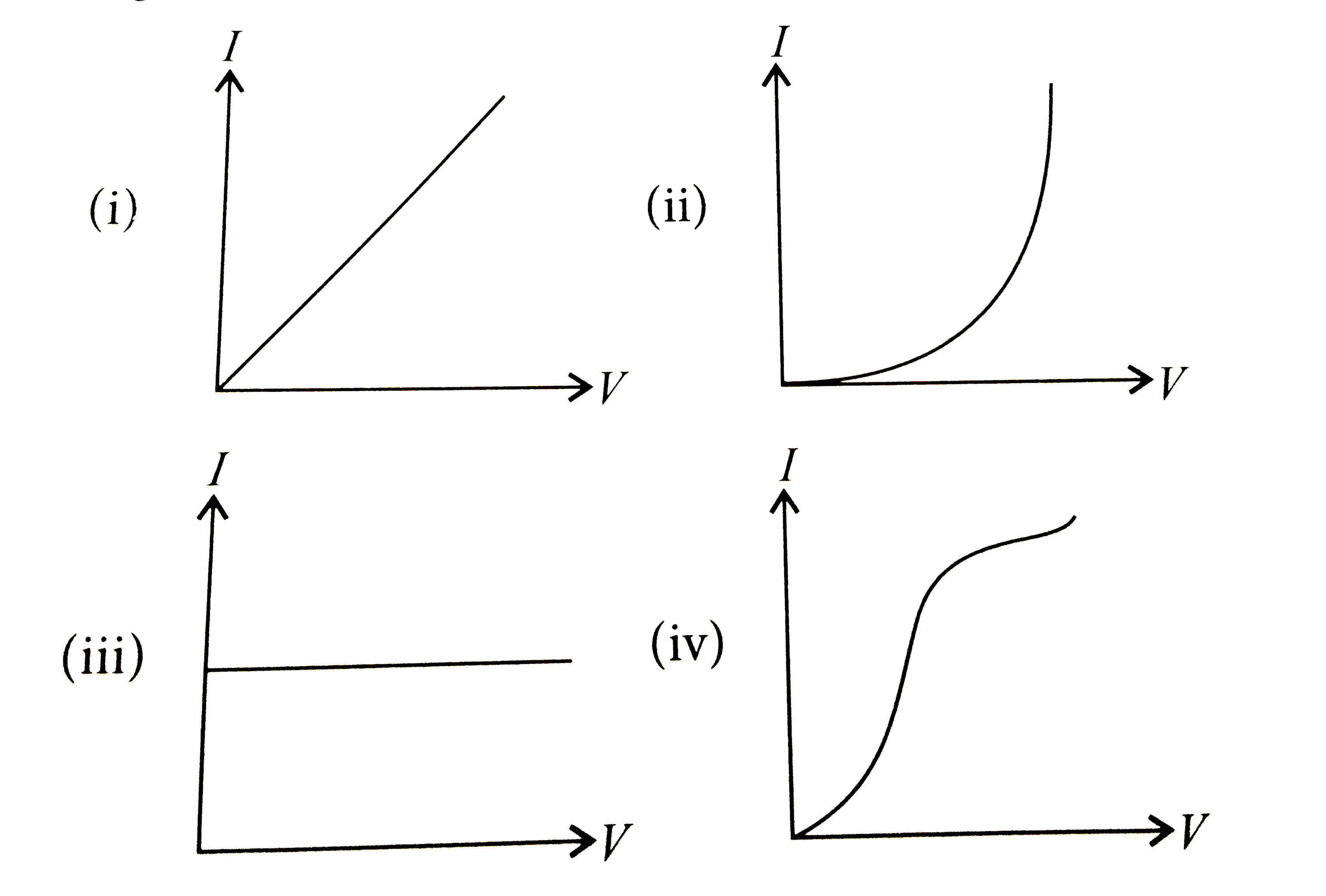
Identify devices that can be used for modulationA(i) and (iii)BOnly (iii)C(ii) and some regions of (iv)DAll the devices can be usedThe I-V characteristics shown in the figure represents
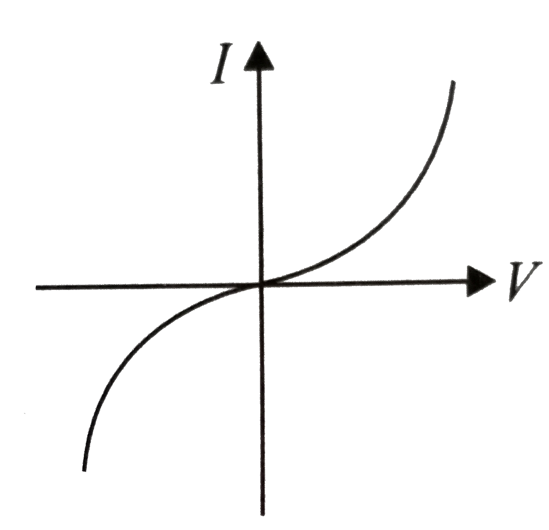 Aohmic conductorsBnon-ohmic conductorsCinsulatorsDsuperconductors
The V-I characteristic of a silicon diode is shown in figure . The resistance of the diode at ID=15 mA is
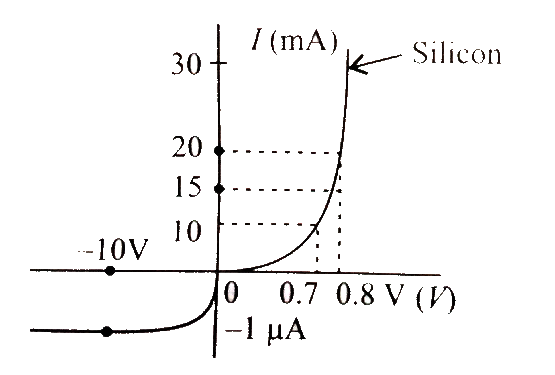 A5ΩB10ΩC2ΩD20Ω
Draw the current-voltage characteristics for the device shown in figure between the terminal A and B.
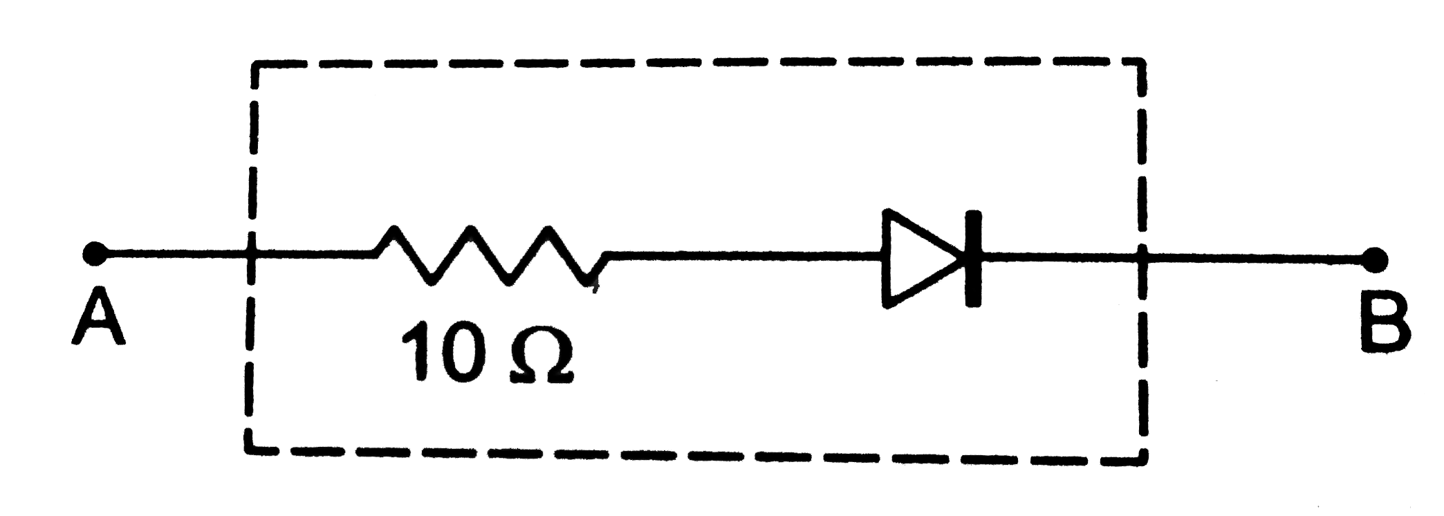

View SolutionName two devices that use plane mirrors.
View SolutionThree devices used for measuring length
View SolutionThe V-I characteristic of a diode is shown in the figure. The ratio of forward to reverse bias resistance is
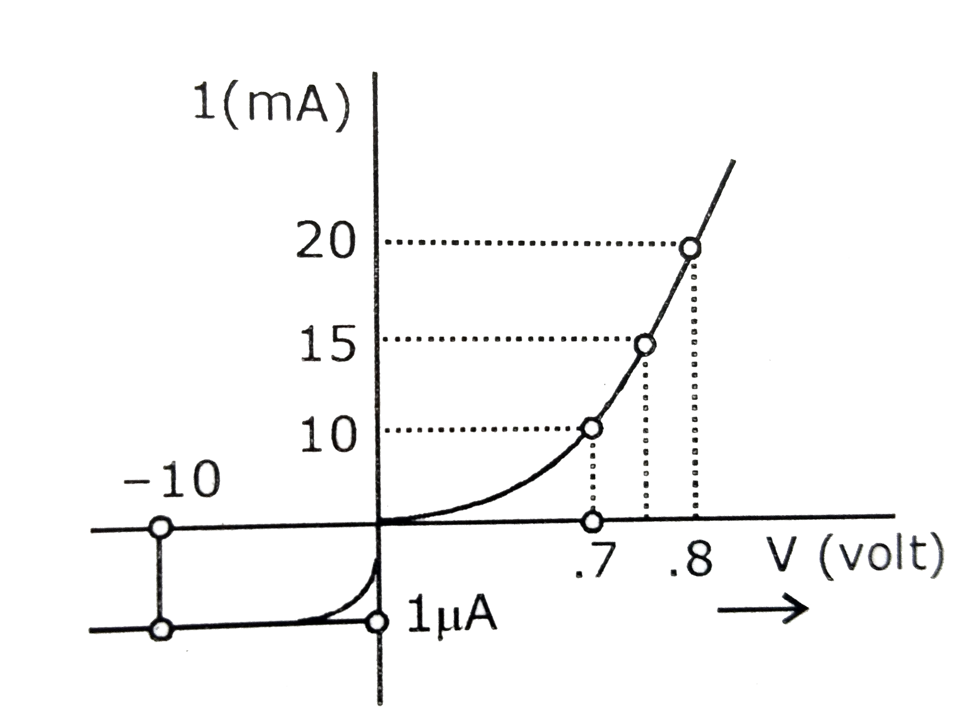
View SolutionThe V-I characteristic of a diode is shown in the figure. The ratio of forward to reverse bias resistance is

View Solution
