An experiment is preformed to determine the I−V characteristics of a Zener diode, which has a protective resistance of R=100Ω, and maximum power of dissipation rating of 1 W. The minimum voltage range of the DC source in the circuit is :-
0−24V
0−12V
0−8V
0.5V
The correct Answer is:A
To determine the minimum voltage range of the DC source in the circuit with a Zener diode, we can follow these steps:
1. Understanding the Circuit:
We have a Zener diode in the circuit with a protective resistance R=100Ω and a maximum power dissipation rating of P=1W.
2. Applying Kirchhoff's Voltage Law:
According to Kirchhoff's voltage law, the total voltage V in the circuit is the sum of the voltage drop across the resistor and the voltage drop across the Zener diode:
V=I⋅R+VD
where I is the current through the circuit and VD is the voltage across the Zener diode.
3. Power Dissipation in the Zener Diode:
The power dissipated in the Zener diode can be expressed as:
PZ=VD⋅I
Given that PZ=1W, we can write:
1=VD⋅I
4. Expressing VD:
Rearranging the power equation gives:
VD=1I
5. Substituting VD into the Voltage Equation:
Substituting VD into the voltage equation, we get:
V=I⋅R+1I
Substituting R=100Ω:
V=100I+1I
6. Finding the Condition for I:
To find the minimum voltage V, we need to minimize the expression 100I+1I. We can do this by taking the derivative and setting it to zero:
dVdI=100−1I2=0
Solving for I:
100=1I2⟹I2=1100⟹I=110=0.1A
7. Calculating Minimum Voltage V:
Now substituting I=0.1A back into the voltage equation:
V=100⋅0.1+10.1=10+10=20V
8. Conclusion:
Therefore, the minimum voltage range of the DC source in the circuit should be greater than 20V. Since the options provided do not include 20V, we choose the next higher option which is 24V.
Final Answer:
The minimum voltage range of the DC source in the circuit is 24V.
---
We have a Zener diode in the circuit with a protective resistance R=100Ω and a maximum power dissipation rating of P=1W.
According to Kirchhoff's voltage law, the total voltage V in the circuit is the sum of the voltage drop across the resistor and the voltage drop across the Zener diode:
V=I⋅R+VD
where I is the current through the circuit and VD is the voltage across the Zener diode.
The power dissipated in the Zener diode can be expressed as:
PZ=VD⋅I
Given that PZ=1W, we can write:
1=VD⋅I
Rearranging the power equation gives:
VD=1I
Substituting VD into the voltage equation, we get:
V=I⋅R+1I
Substituting R=100Ω:
V=100I+1I
To find the minimum voltage V, we need to minimize the expression 100I+1I. We can do this by taking the derivative and setting it to zero:
dVdI=100−1I2=0
Solving for I:
100=1I2⟹I2=1100⟹I=110=0.1A
Now substituting I=0.1A back into the voltage equation:
V=100⋅0.1+10.1=10+10=20V
Therefore, the minimum voltage range of the DC source in the circuit should be greater than 20V. Since the options provided do not include 20V, we choose the next higher option which is 24V.
The minimum voltage range of the DC source in the circuit is 24V.
Topper's Solved these Questions
- SEMICONDUCTORSBOOK - ALLENCHAPTER - SEMICONDUCTORSEXERCISE - Part-3(Exercise-3)
27 Videos
- PHYSICAL WORLD, UNITS AND DIMENSIONS & ERRORS IN MEASUREMENT BOOK - ALLENCHAPTER - PHYSICAL WORLD, UNITS AND DIMENSIONS & ERRORS IN MEASUREMENT EXERCISE - EXERCISE-IV
8 Videos
- WAVES AND OSCILLATIONSBOOK - ALLENCHAPTER - WAVES AND OSCILLATIONSEXERCISE - Part-1(Exercise-05)[B]
42 Videos
Similar Questions
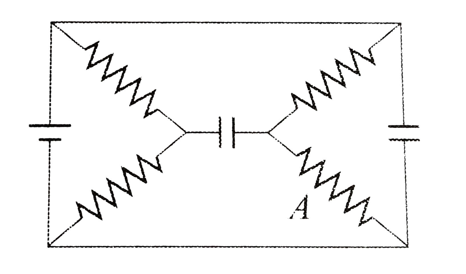
Each resistor in the following circuit has a resistance of 2MΩ and the capacitors have capacitances of 1μF. The battery voltage is 3V. The voltage across the resistor A in the following circuit in steady state is
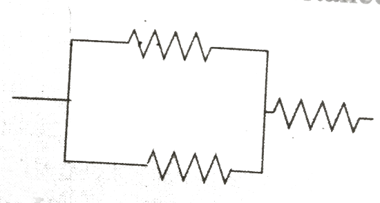
View SolutionEach of three resistors in fig. 7.12 has a resistance of 2Ω and can dissipate a maximum of 18W without becoming excessively heated. Find the maximum power the circuit can dissipate.
View Solution
Knowledge Check
A Zener diode is specified having a breakdown voltage of 9.1 V with a maximum power dissipation of 364 mW. What is the maximum current that the diode can handle.
A40 mAB60 mAC50 mAD45 mA
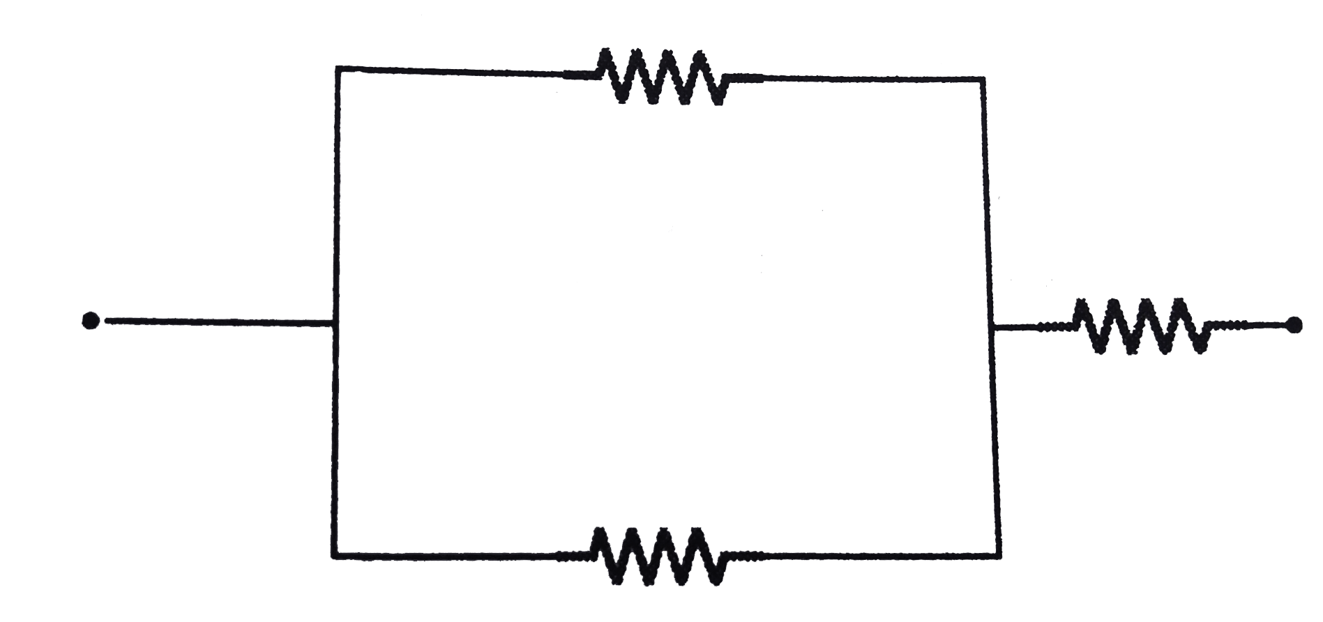
Each of three resistors in figure has a resistance of 2.4Ω and can dissipate a maximum of 36 W without becoming excessively heated. What is the maximum power the circuit can dissipate?
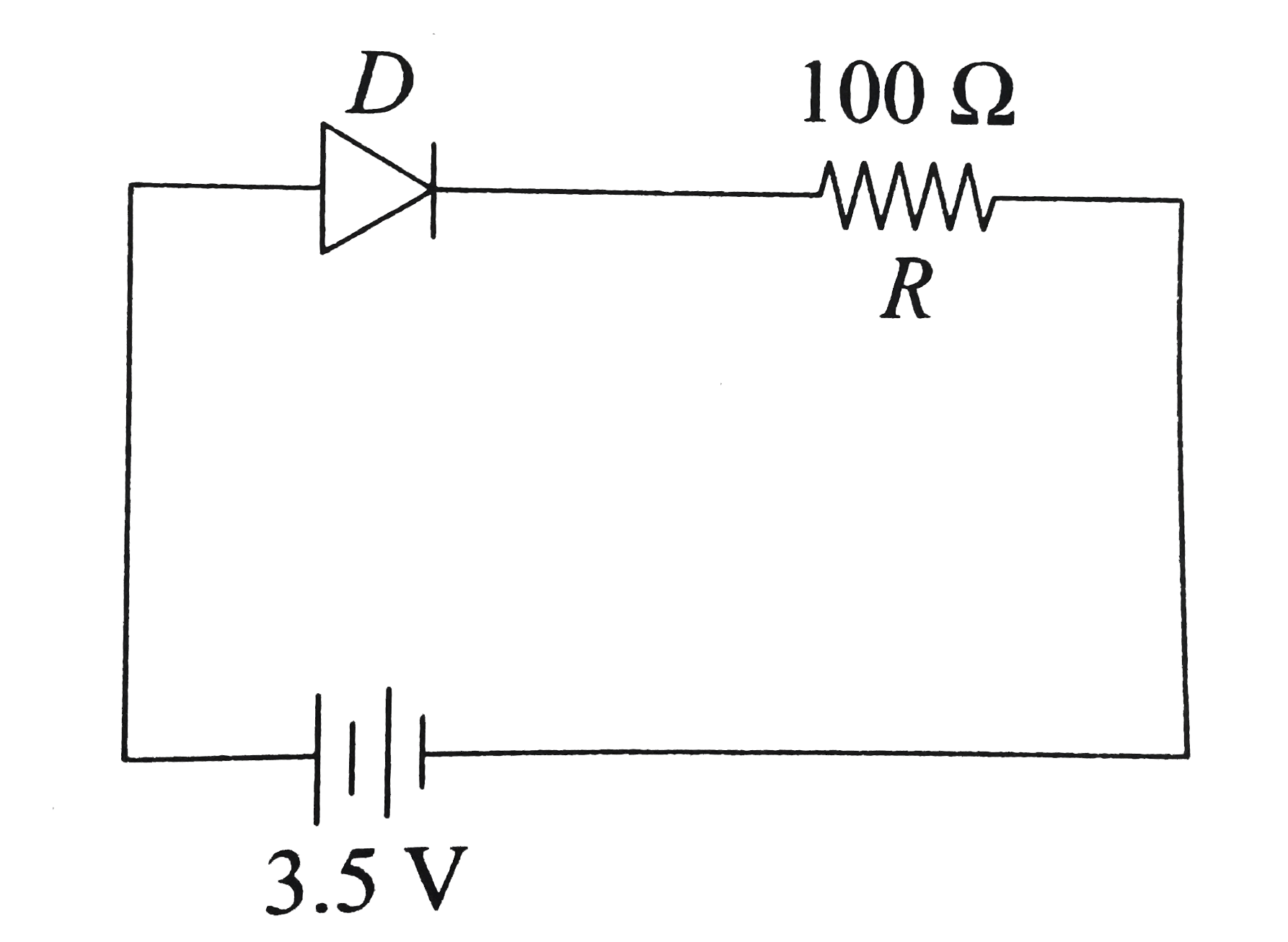
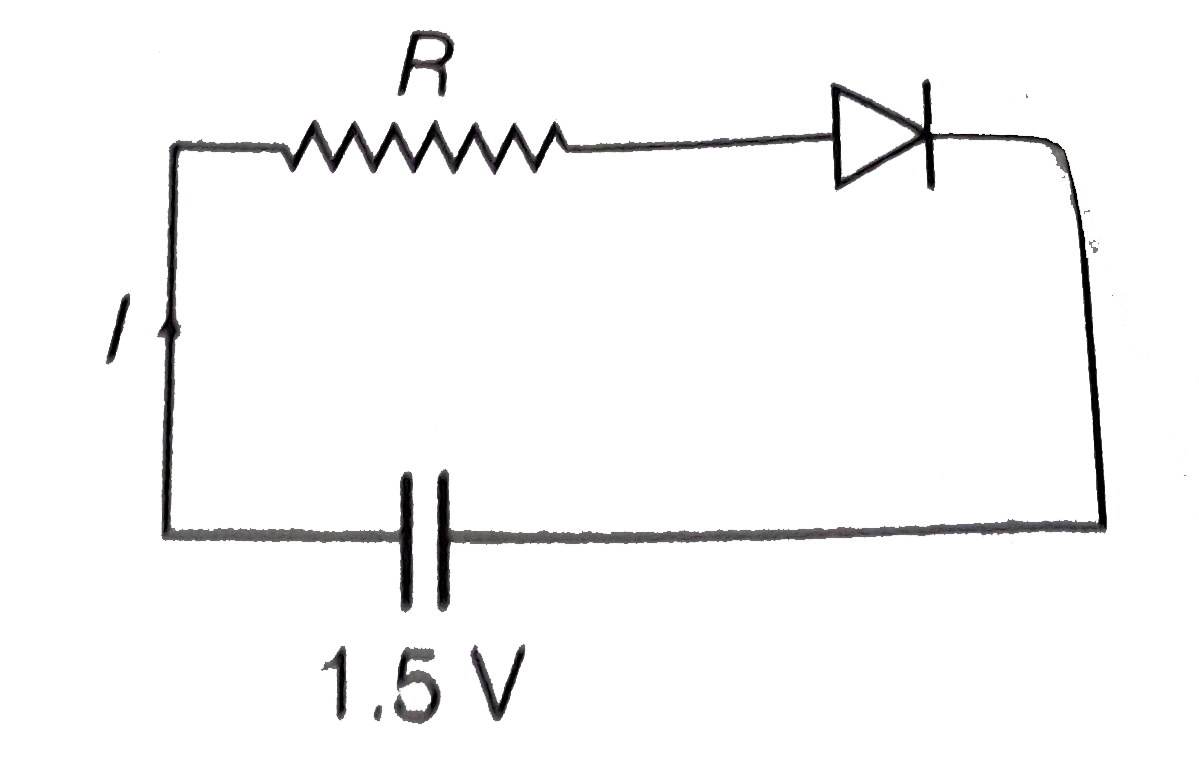
View SolutionIn the given figure, a diode D is connected to an external resistance R=100Ω and an emf of 3.5V. If the barrier potential developed across the diode is 0.5V, the current in the circuit will be :
View SolutionAn electric motor which is loaded has an effective resistance of 30Ω and an inductive reactance of 40Ω . If the motor is powered by a source with a maximum voltage of 420 V, the maximum current is
View SolutionThe diode used at a constant potential drop of 0.5 V at all currents and maximum power rating of 100 mW. What resistance must be connected in series diode, so that current in circuit is maximum?
View SolutionA Zener diode with a breakdown voltage of 4 V is connceted in sereis with a resistance R to a battery of emf 10 V. The maximum power dissipation rating for the Zener diode is 1 W. The value of R to ensure maximum power dissipation across the diode is
View SolutionThe 6 V Zener diode shown in the figure has negligible resistance and a knee current of 5 mA. The minimum value of R (in Ω) so that the voltage across it does not fall below 6 V is
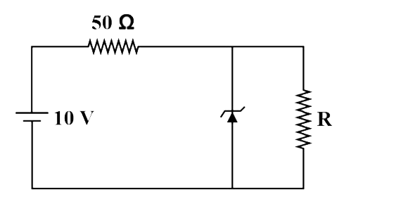
View SolutionThe 6 V Zener diode shown in the figure has negligible resistance and a knee current of 5 mA. The minimum value of R (in Ω) so that the voltage across it does not fall below 6 V is

View Solution
