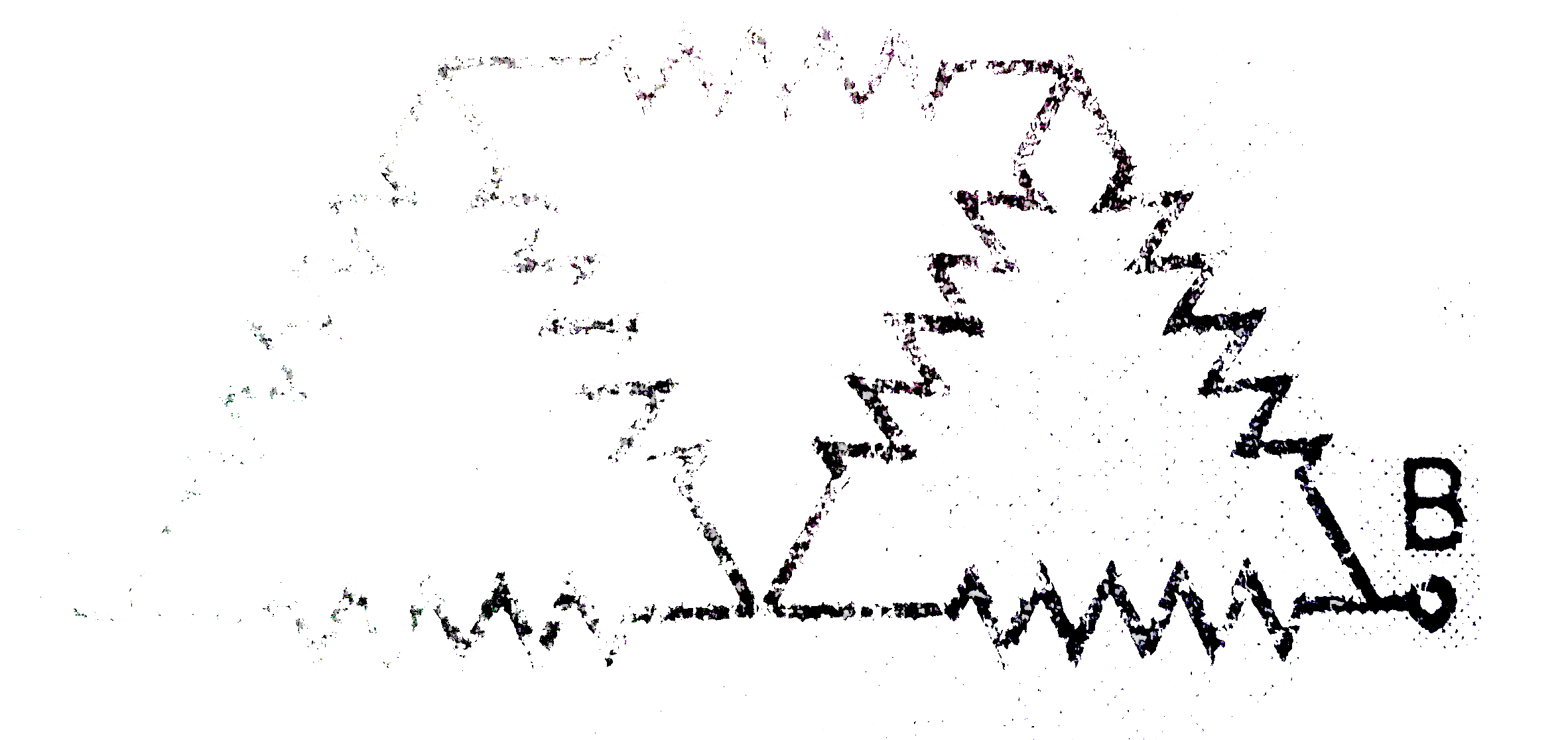
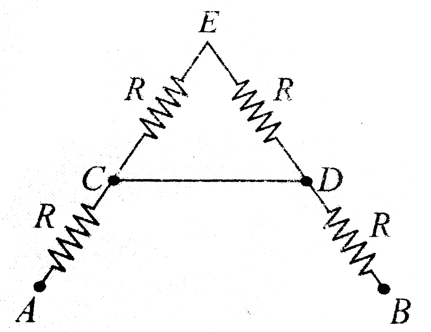
Each resistance is of 1Ω in the circuit diagram shown in figure. Find out equivalent resistance between A and B.
If we use ground as internal frame as we usually do, solutiona of the problem becomes quite involved. Therefore, we prefer the center of mass frame, in which mass center remains at rest.

In the adjacent figure is shown horizontal position of mass center (CM) by dashed line. It remains unchanged in center of mass frame.
Mass center of two particle system divides separation between them in reciprocal ratio of the masses, therefore displacements x1 and x2 of the blocks must also be in reciprocal ratio of their masses. The extension x is sum of displacements x1 and x2 of the blocks as shown in the figure.When extension of the spring achieves its maximum value, both the block must stop receding away from the mass center, therefore, velocities of both the blocks in center of mass must be zero, nrgative work done by spring forces becomes equal to increase in potential energy and work done by applied force evidently becomes Fx1.
Using above fact in applying work energy theorem on the system relative to the cente of mass frame, we obtain
Ki+Wi→f=Kf→0+Wi→f,springforce+Wi→f,F=0
−(0−12kx2)+FMxm+m=0
x=2FMk(m+m)
Topper's Solved these Questions
- CURRENT ELECTRICITYBOOK - ALLENCHAPTER - CURRENT ELECTRICITYEXERCISE - EXERCISE-III
26 Videos
- CURRENT ELECTRICITYBOOK - ALLENCHAPTER - CURRENT ELECTRICITYEXERCISE - EXERCISE-IV A
32 Videos
- CIRCULAR MOTIONBOOK - ALLENCHAPTER - CIRCULAR MOTIONEXERCISE - EXERCISE (J-A)
6 Videos
- GEOMETRICAL OPTICSBOOK - ALLENCHAPTER - GEOMETRICAL OPTICSEXERCISE - subjective
14 Videos
Similar Questions
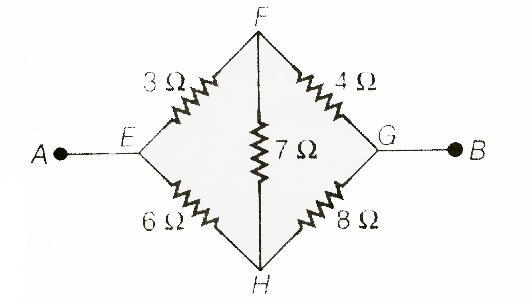
A bridge circuit is shown in figure. The equivalent resistance between A and B will be
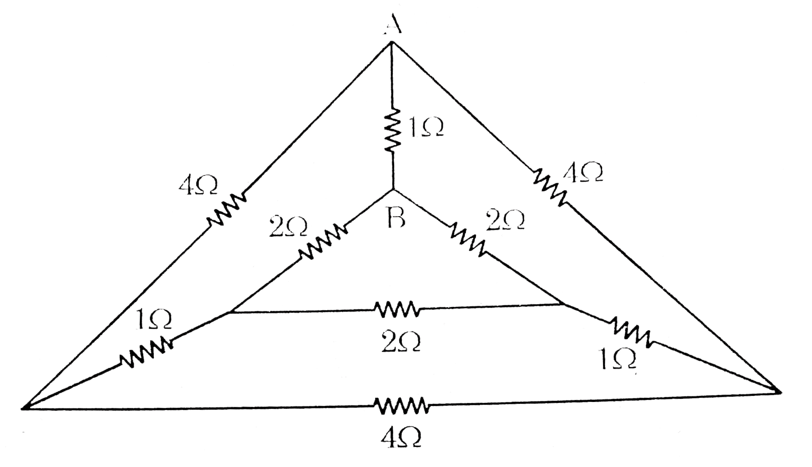
View SolutionConsider the circuit as shown in figure. The equivalent resistance between A and B is
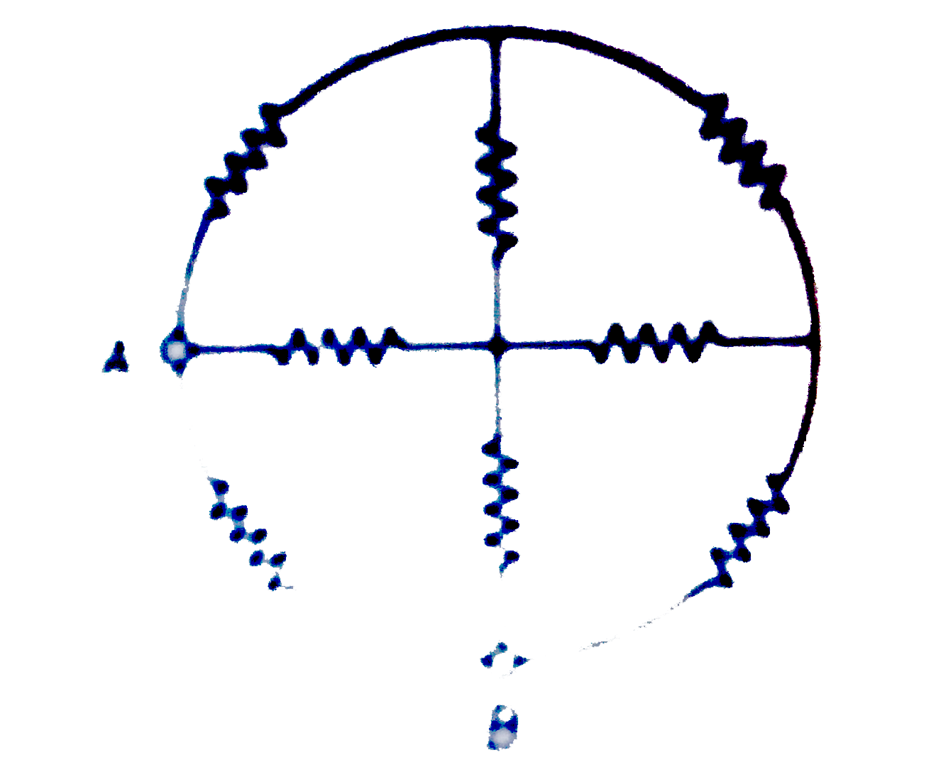
View SolutionEight resistances each of resistance 5Ω are connected in the circuit as shown in figure. The equivalent resistance between A and B is
View SolutionIn the circuit shown in figure, the equivalent resistance between A and B is __________ Ω.
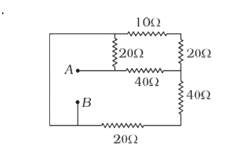
View SolutionFor the circuit shown in figure given below, the equivalent resistance points A and B is
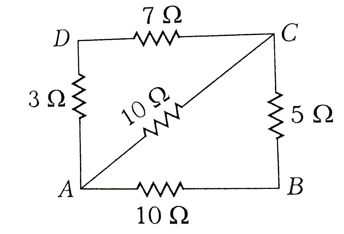
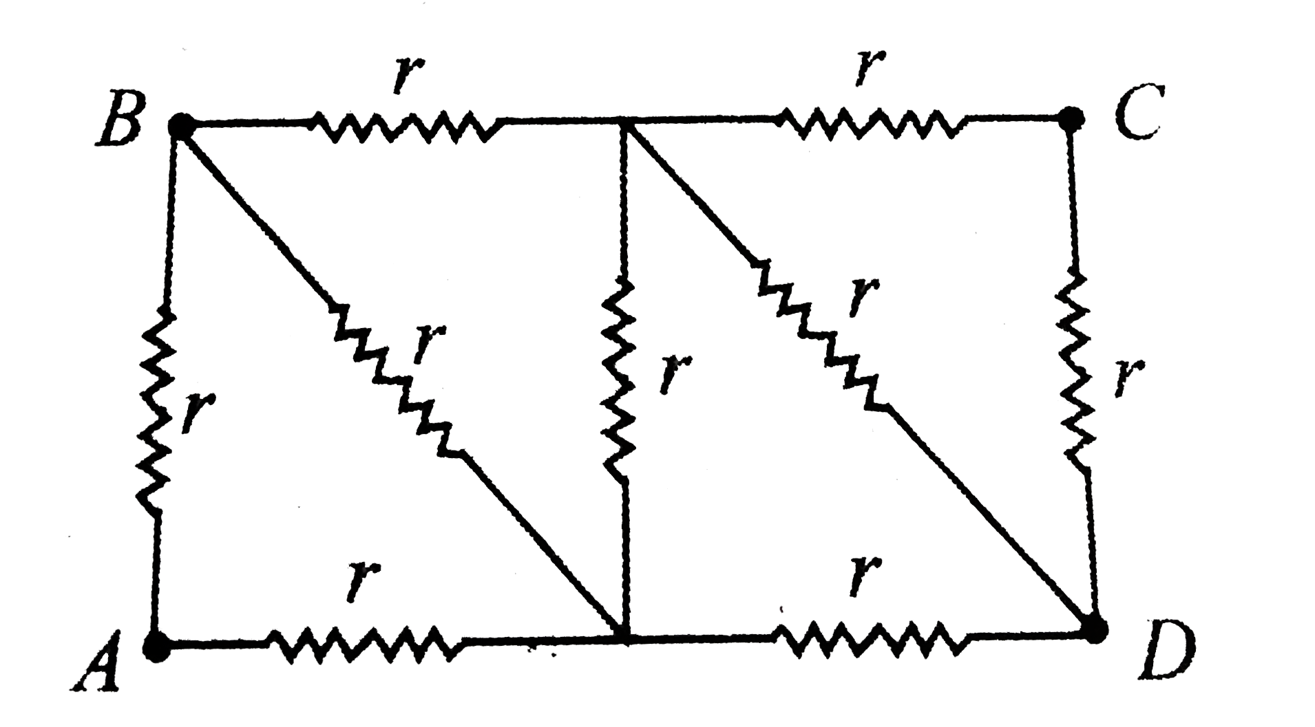
View SolutionEach resistance of the circuit shown in figure is r. The equivalent resistance between A and B is
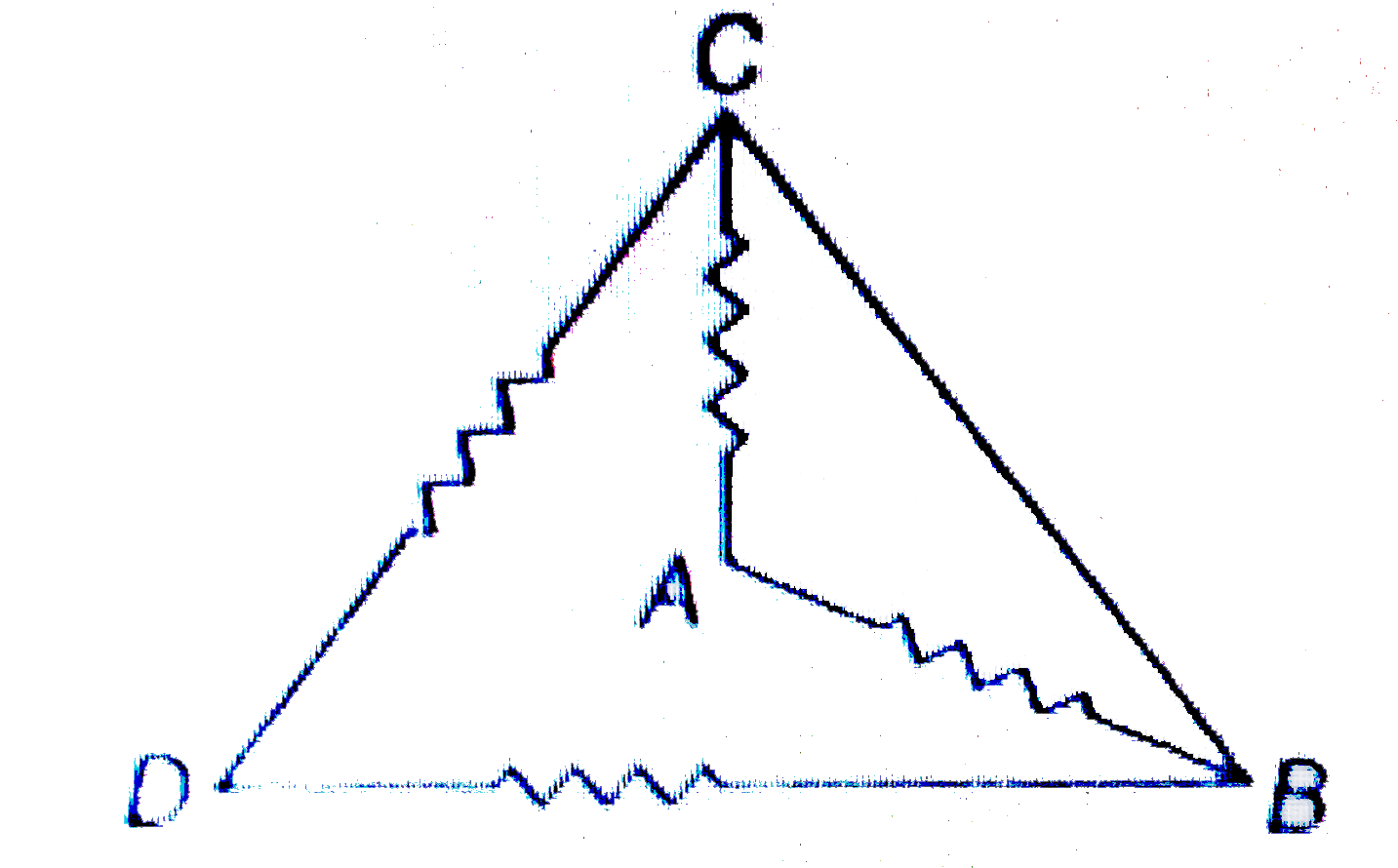
View SolutionFive resistance, each of 5Ω are connected as shown in figure. Find the equivalent resistance between points (1) A and B , (2) A and C .
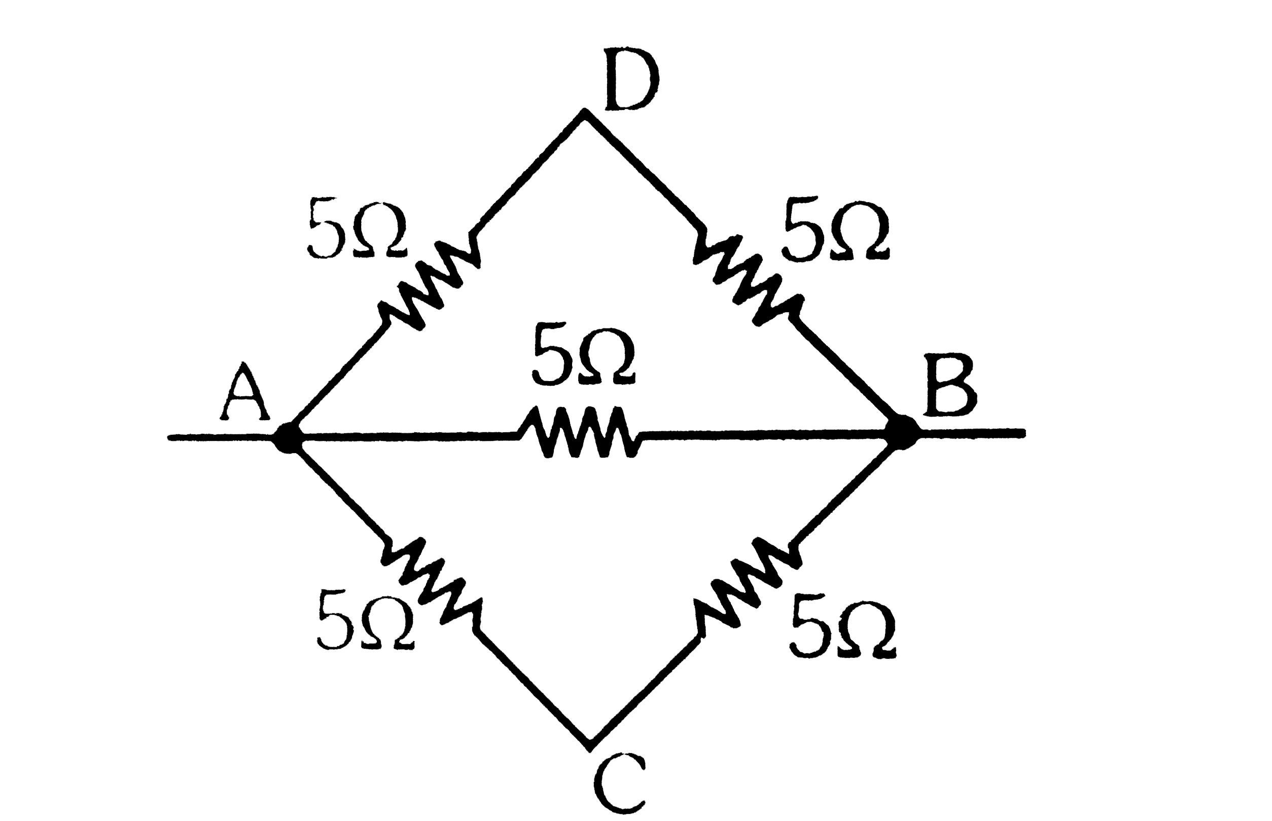
View SolutionFour identical resistances each having value R are arranged as shown in Figure. Find the equivalent resistance between A and B.
View SolutionFor the circuit shown in fig. the equivalent resistance between A and C is
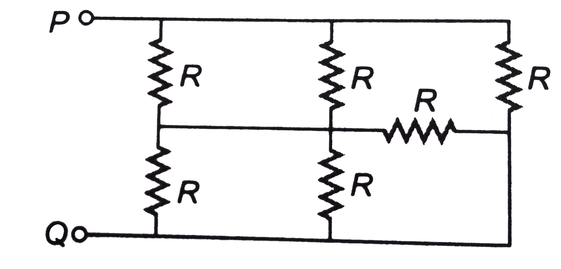
View SolutionIn the circuit shown in figure R=55Ω the equivalent resistance between the point P and Q is
View Solution
