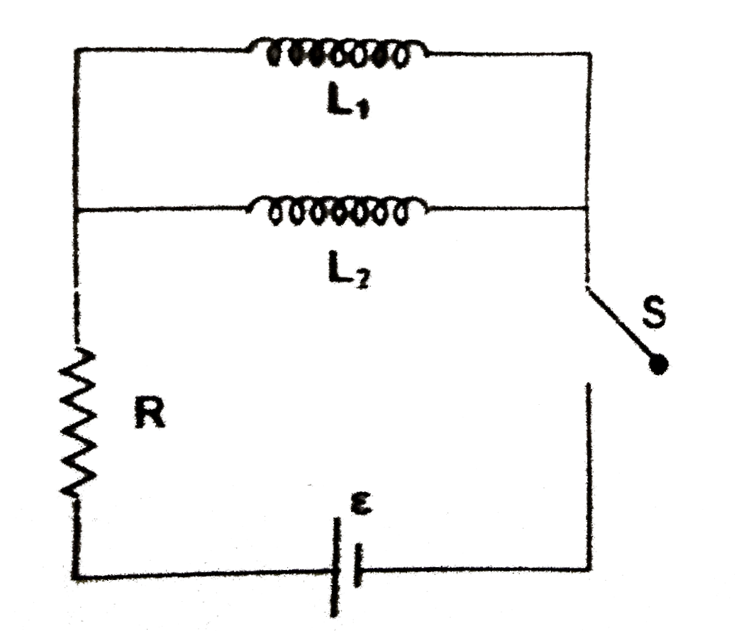
In the circuit shown, switch's is closed at t=0. then the ratio U1U2 of potential energy stored in the inductors L1 and L2 in steady state is
L1L2
L2L1
(L1L2)2
(L2L1)2
The correct Answer is:B
L1di1dt=L2di2dt ltbr> L1i1∫0di1=L2i2∫0di2
L1i1=L2i2 .(i)
i1+i2=i …(ii)
i1(1+L1L2)=i
⇒i1=(L2L1+L2)i and i2=(L1L1+L2)i ltbr> ∴U1U2=12L1i2112L2i22=L1L22L2L21=L2L1
Similar Questions
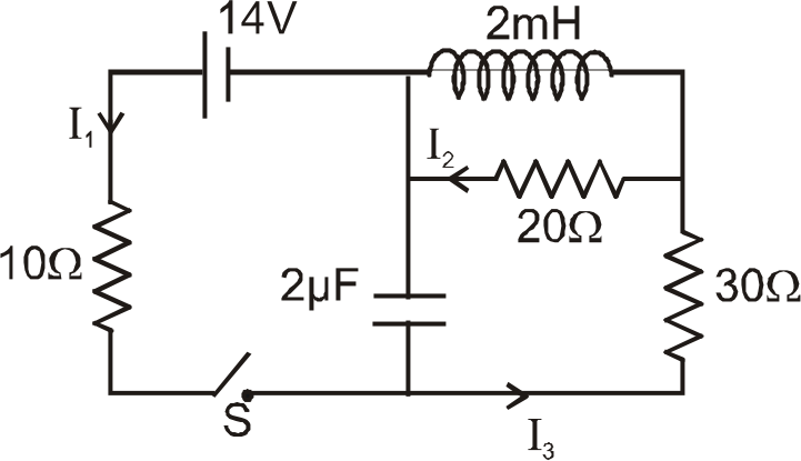
In the circuit shown, the switch is closed at t=0, the currents I1,I2 and I3 are
 View Solution
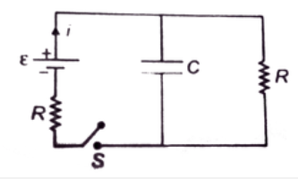
In the circuit shown, the switch is closed at t=0. Select the correct alternative(s)
 View Solution
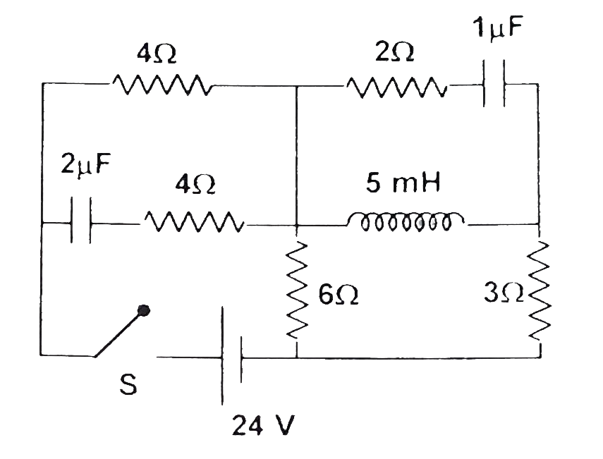
In the circuit shown, the switch 'S' is closed at t=0. Then the current through the battery steady state reached is
 View Solution
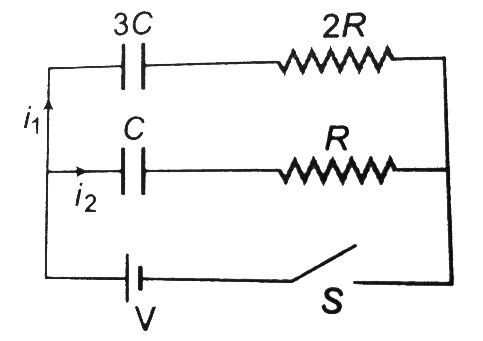
In the circuit shown switch S is closed at t=0. Let i1 and i2 be the current at any finite time t then the ratio i1i2
 View Solution
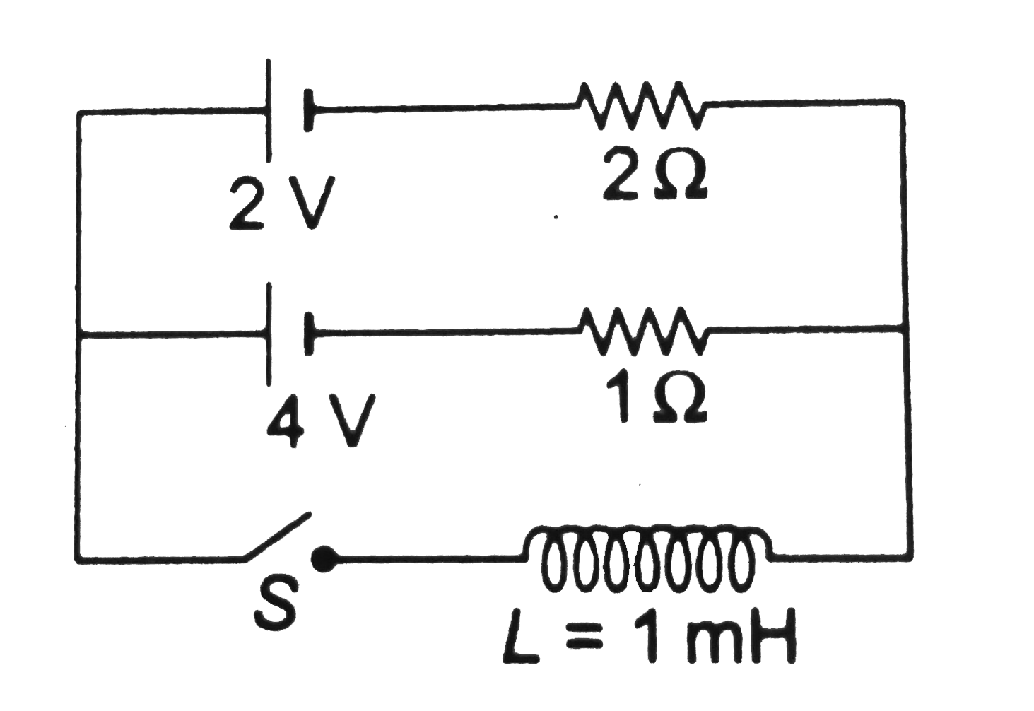
In the circuit shown, switch S is closed at time t=0. Find the current through the inductor as a function of time t.
 View Solution
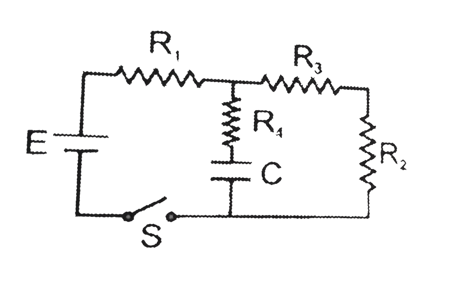
In the circuit shown in figure the switch S is closed at t = 0. A long time after closing the switch
 View Solution
In the circuit shown in figure switch S is closed at time t=0
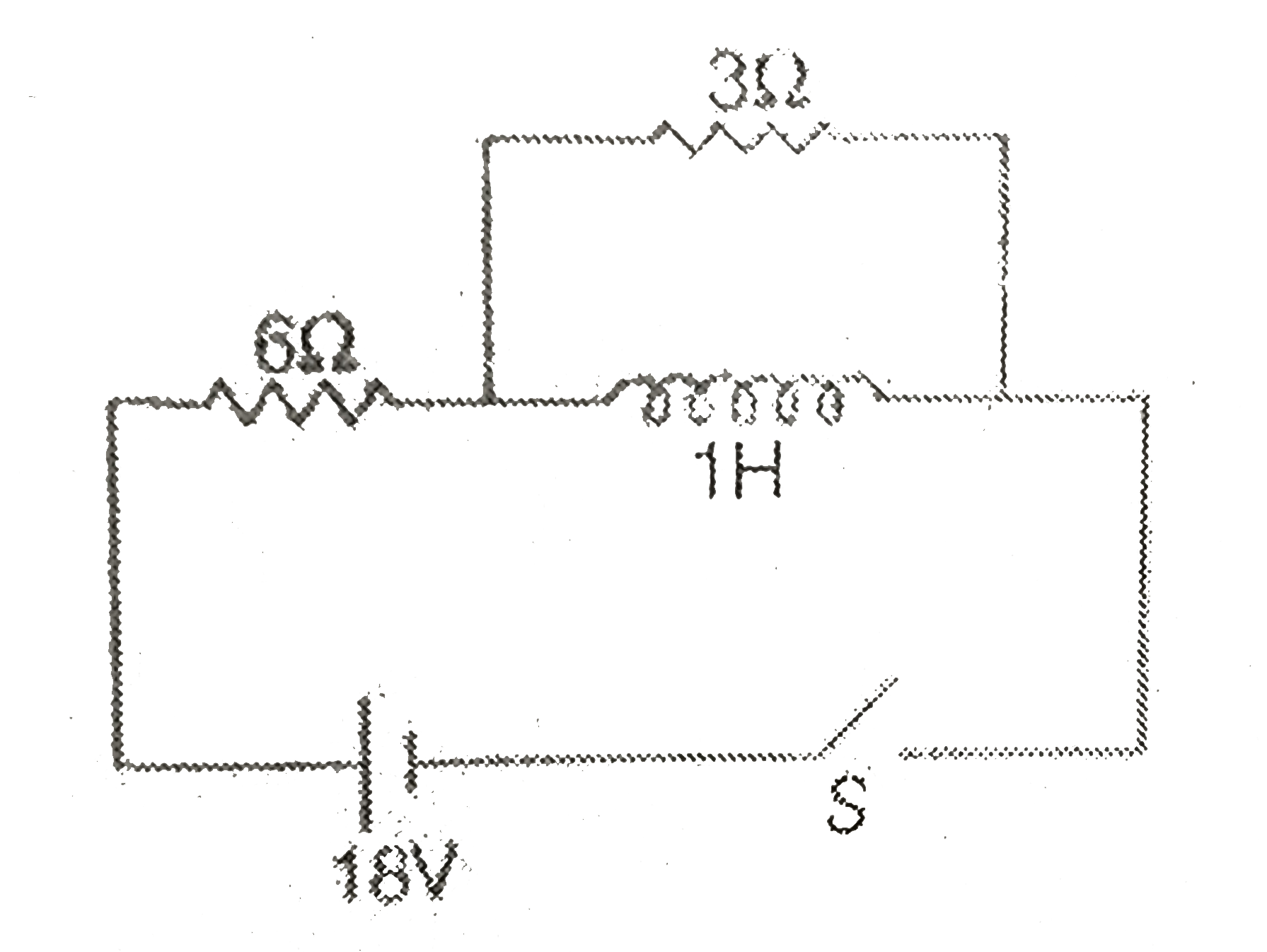
At what time current through 3Ω resistance and 1H inductor are equal?View SolutionSwitch is closed at t=0 then the current in the circuit at t=L2R is
_PHY_E06_157_Q01.png) View Solution
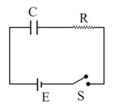
View SolutionThe capacitor shown in the figure is initially unchanged, the battery is ideal. The switch S is closed at time t= 0, then the time after which the energy stored in the capacitor becomes one - fourth of the energy stored in it in steady - state is :
 View Solution
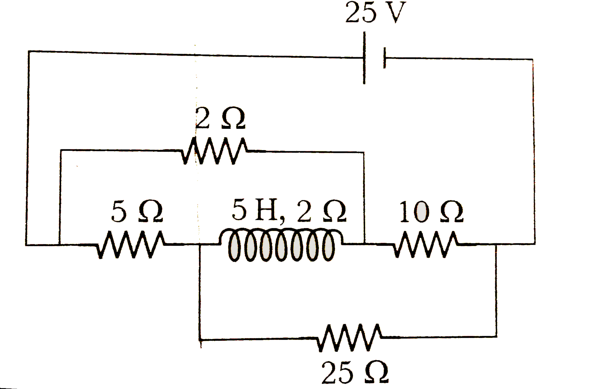
In the circuit shown , what is the energy stored in the coil at steady state?
 View Solution

