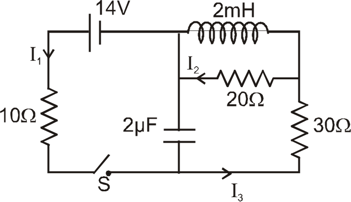
In the circuit shown, the switch is closed at t=0. Select the correct alternative(s)
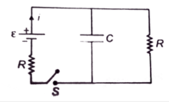
At t=0,
At t=0 ,
At steady state, charge on the capacitor is
The current at any instant is given by
The correct Answer is:(1, 3, 4)
Step by step video & image solution for In the circuit shown, the switch is closed at t=0. Select the correct alternative(s) by Physics experts to help you in doubts & scoring excellent marks in Class 12 exams.
Updated on:21/07/2023Topper's Solved these Questions
- CURRENT ELECTRICITYBOOK - AAKASH INSTITUTE ENGLISHCHAPTER - CURRENT ELECTRICITYEXERCISE - ASSIGNMENT SECTION-D( LINKED COMPREHENSION TYPE QUESTIONS)
3 Videos
- CURRENT ELECTRICITYBOOK - AAKASH INSTITUTE ENGLISHCHAPTER - CURRENT ELECTRICITYEXERCISE - ASSIGNMENT SECTION-D( LINKED COMPREHENSION TYPE QUESTIONS) Comprehension - II
5 Videos
- CURRENT ELECTRICITYBOOK - AAKASH INSTITUTE ENGLISHCHAPTER - CURRENT ELECTRICITYEXERCISE - ASSIGNMENT SECTION-B(OBJECTIVE TYPE QUESTION ))
44 Videos
- COMMUNICATION SYSTEMS BOOK - AAKASH INSTITUTE ENGLISHCHAPTER - COMMUNICATION SYSTEMS EXERCISE - ASSIGNMENT SECTION D (Assertion-Reason)
10 Videos
- DUAL NATURE OF RADIATION AND MATTER BOOK - AAKASH INSTITUTE ENGLISHCHAPTER - DUAL NATURE OF RADIATION AND MATTER EXERCISE - ASSIGNMENT (SECTION-D)
10 Videos
Similar Questions
In the circuit shown in the figure, switch S is closed at time t=0. Select the correct statements.
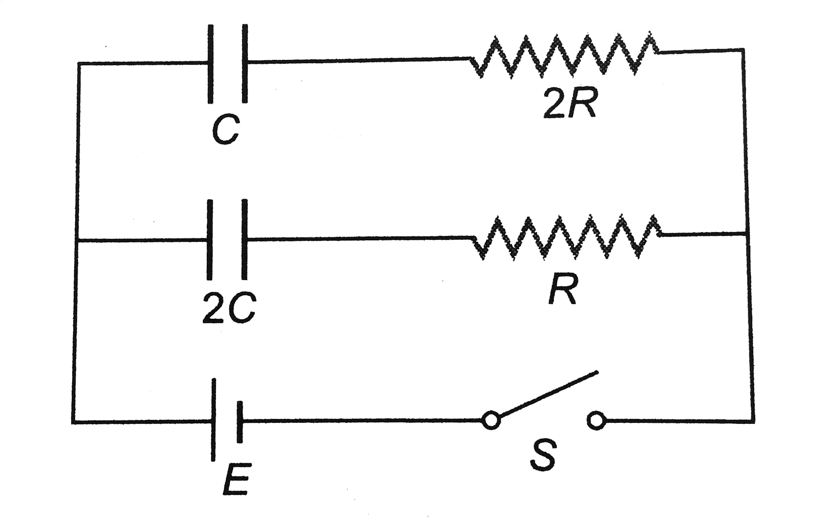
View SolutionIn the circuit shown in the figure, switch S is closed at time t=0. Select the correct statements.

View SolutionA parallel pate capacitor of capacitance ‘C’ has charge on its plates initially as shown in the figure. Now at the switch ‘S’ is closed. Select the correct alternative (s) for this circuit diagram.
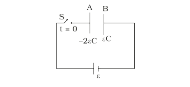
View SolutionIn the circuit shown, the switch 'S' is closed at t=0. Then the current through the battery steady state reached is
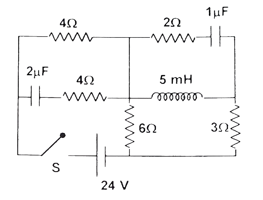
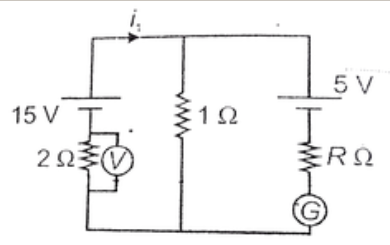
View SolutionIn the circuit shown, readint of galvanometer is zero. Select the correct alternative(s)
View SolutionAn inductor L and a resistance R are connected in series with a battery of emf E and a switch. Initially the switch is open. The switch is closed at an instant t = 0. Select the correct alternatives
View SolutionIn the circuit shown, the switch is closed at t=0, the currents I1,I2 and I3 are
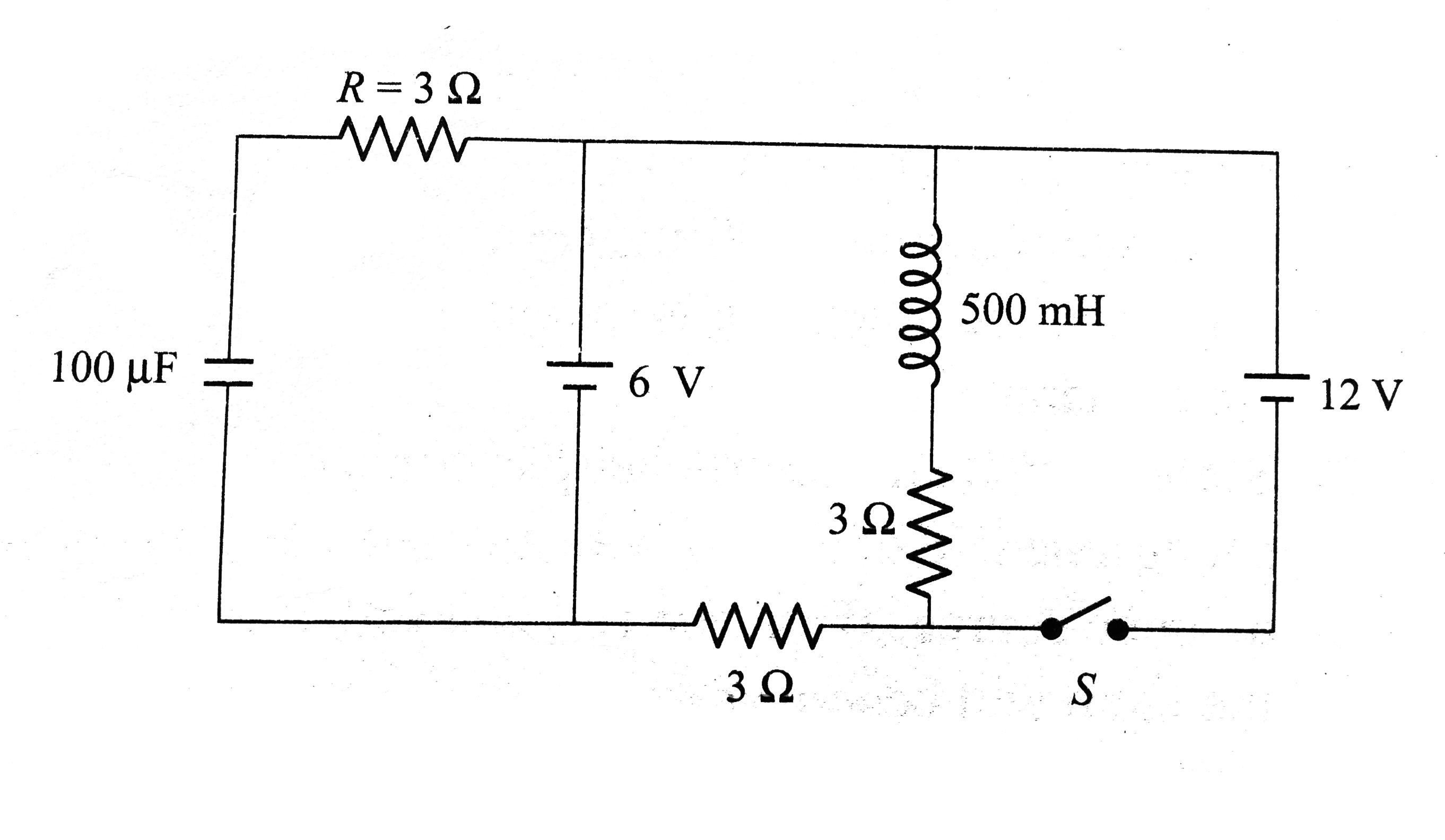
View SolutionIn the given circuit Fig the switch is closed at t=0. Choose the correct answers.
View SolutionIn the given circuit, the switch S is closed at time t=0 then select the correct statement for current l in resistance PQ as shown in the figure
_PHY_E05_091_Q01.png)
View Solution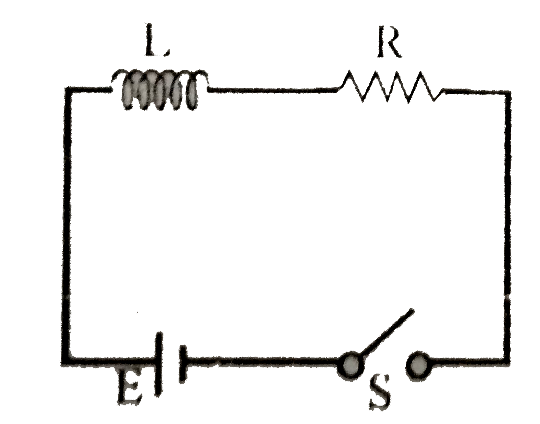
In the LR circuit as shown in figure, te switch is closed at t=0, mark the incorrect statement of the following
View Solution
