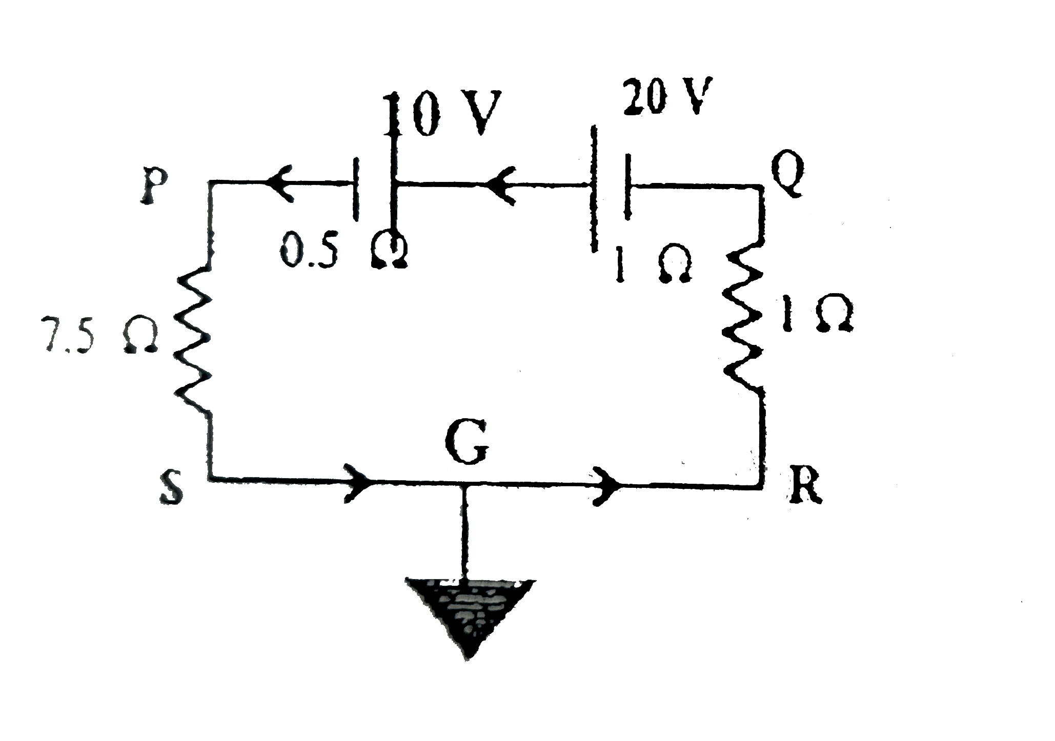
In the circuit shown in the adjacent figure
A
the potential at P is −7.5V
B
the potential at Q is −1V
C
the potential at R is zero
D
the potential at S is zero
Video Solution
Text Solution
The current in the circuit I=(20−10)(7.5+.5+1+1)=1010=1Amp
The potential difference across PSVPS=7.5×1=7.5V
The potential difference across QR, VQR=1×1=1V
As point G is connected to earth hence potentials of R and S is zero.
The direction of the current in the circuit is from P to S, hence point P is at higher potential.
∴Vp=7.5V
similarly VQ=−1V
|
Similar Questions
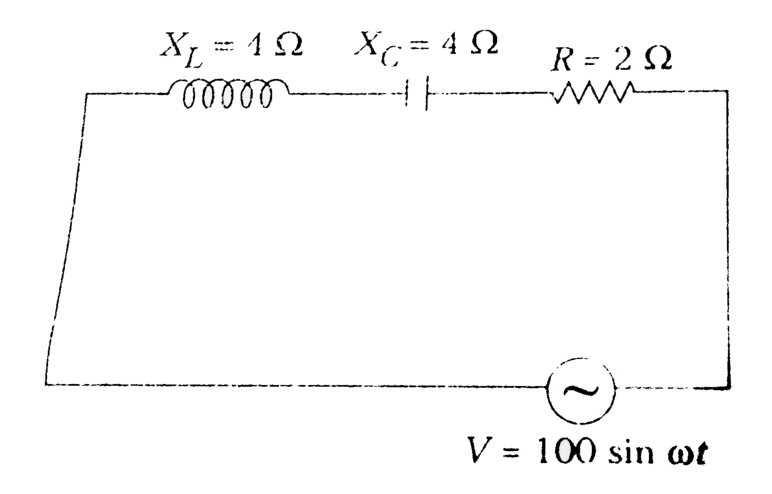
Which of the following statements is correct regarding the AC circuit shown in the adjacent figure?
View SolutionCurrent through the battery in the circuit shown in the figure
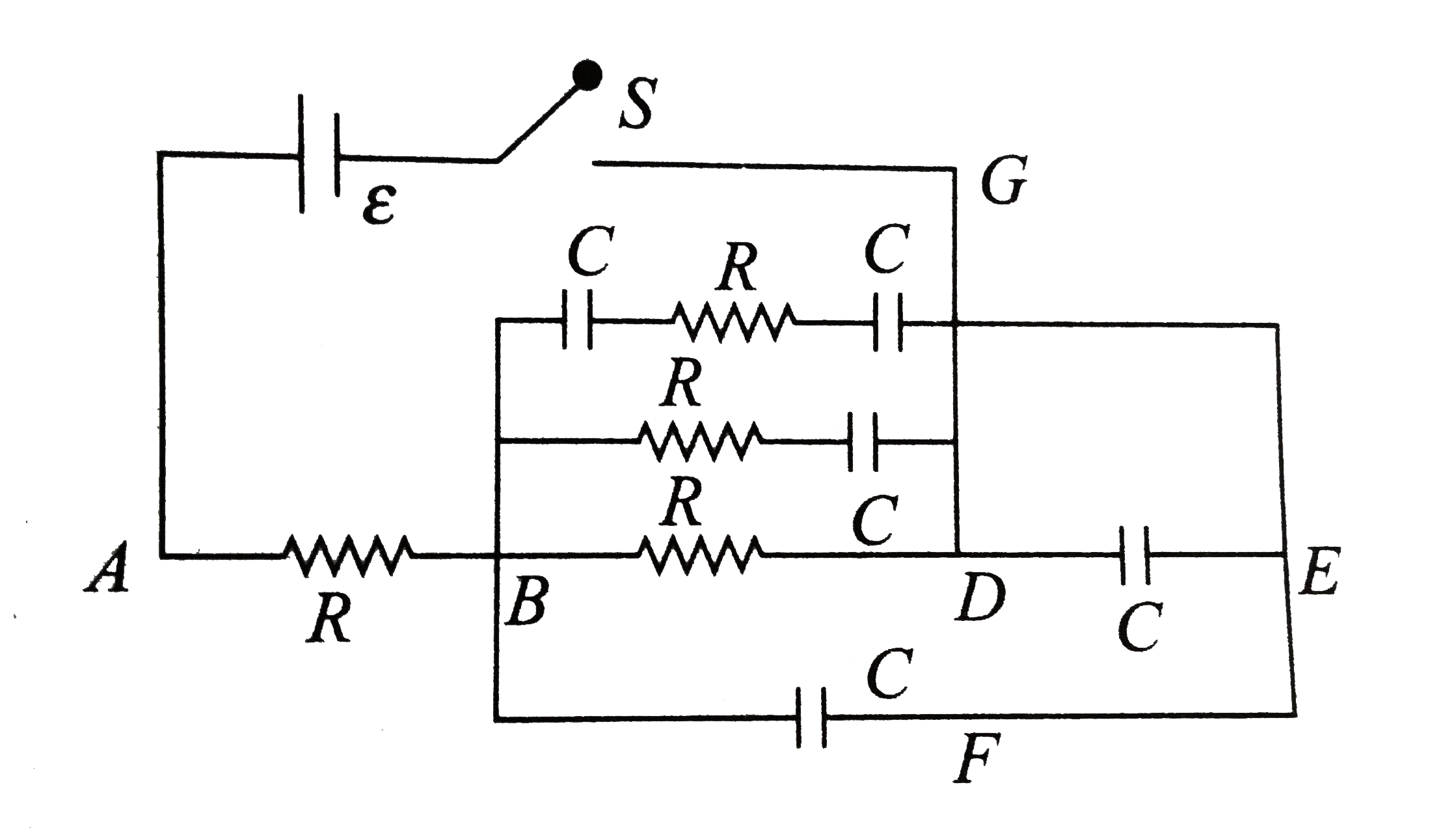
View SolutionIn the circuit shown in figure
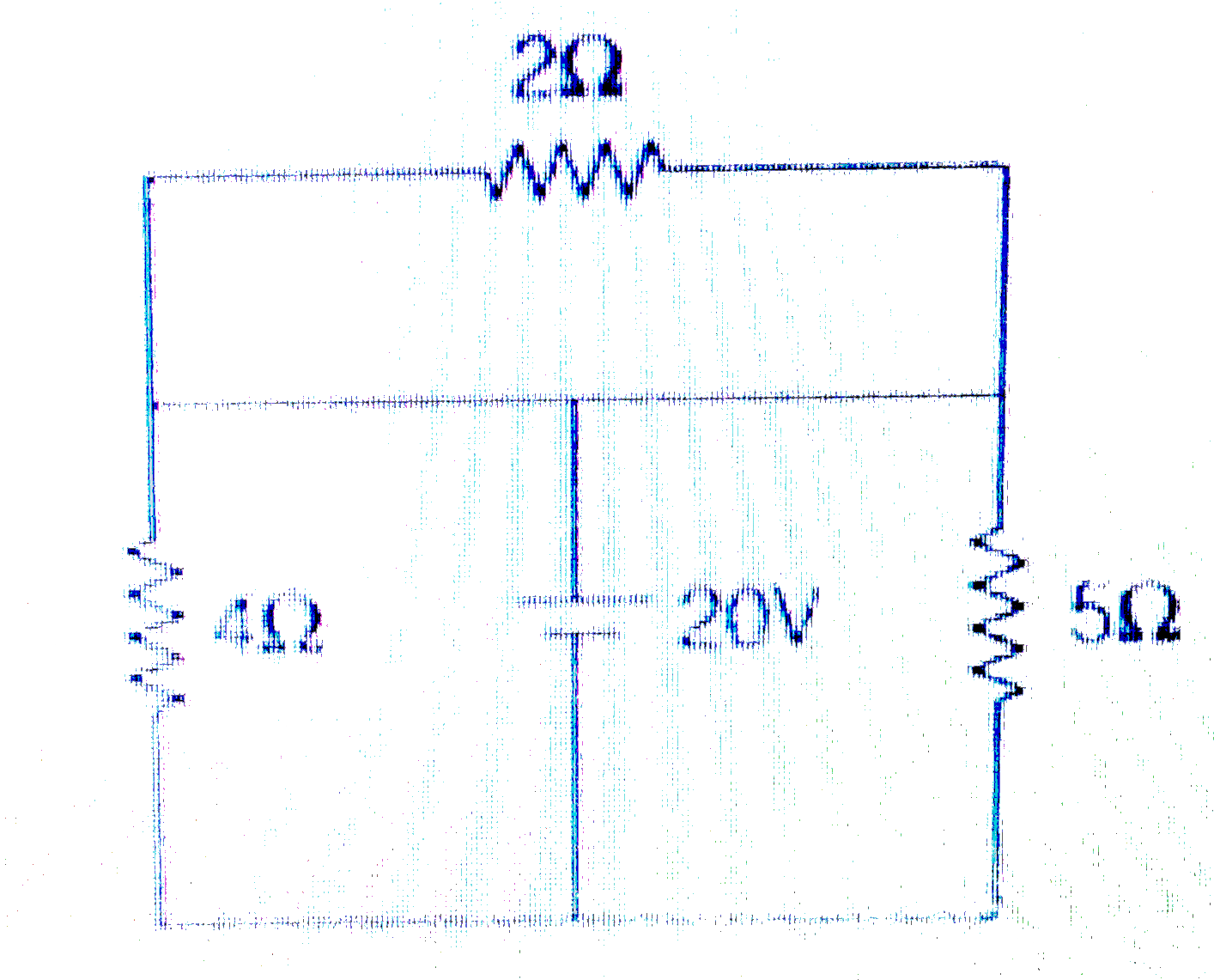
View SolutionIn the circuit shown in figure
View SolutionIn the circuit shown in figure
View SolutionIn the circuit shown in figure
View SolutionIn the circuit shown in the figure,
View SolutionIn the circuit shown in figure
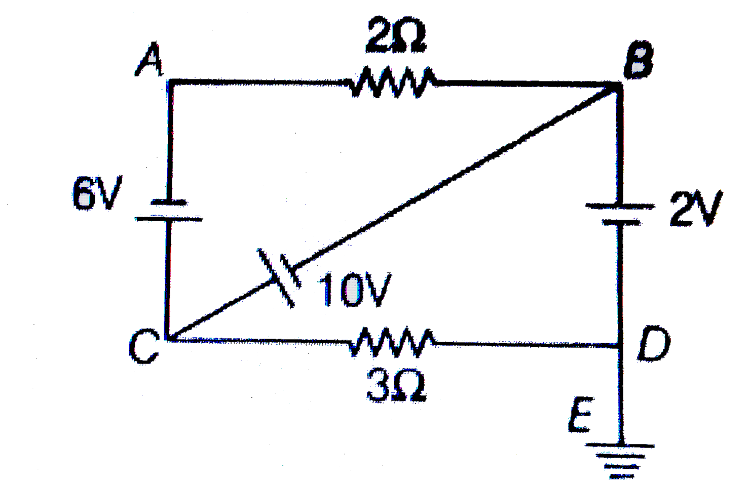
View SolutionIn the circuit shown in figure
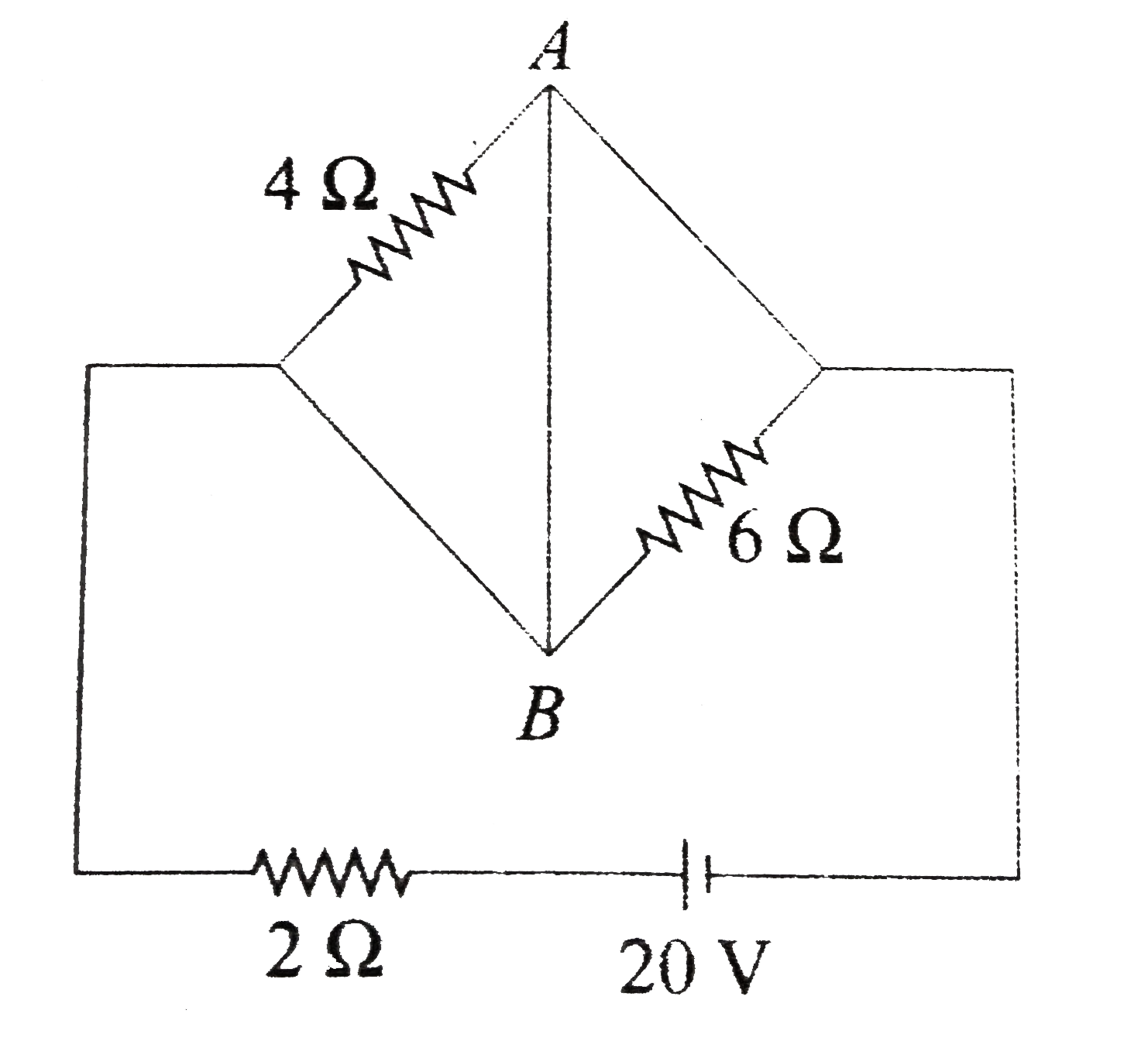
View SolutionIn the circuit shown in figure
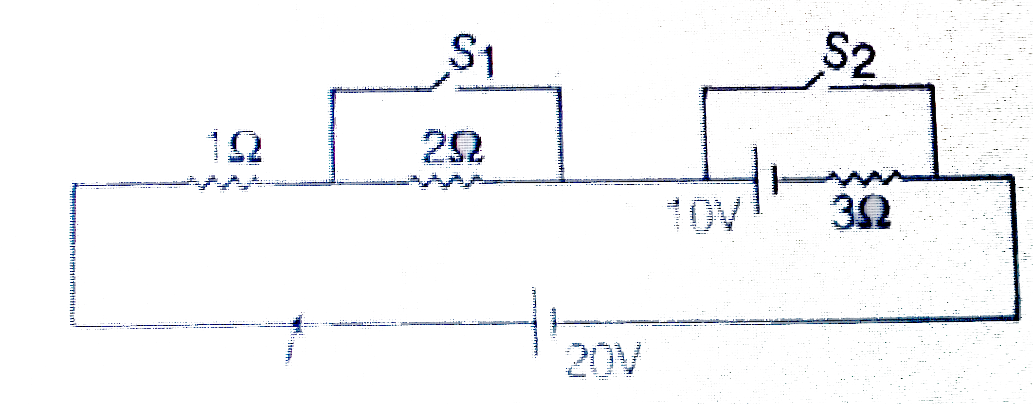
View Solution