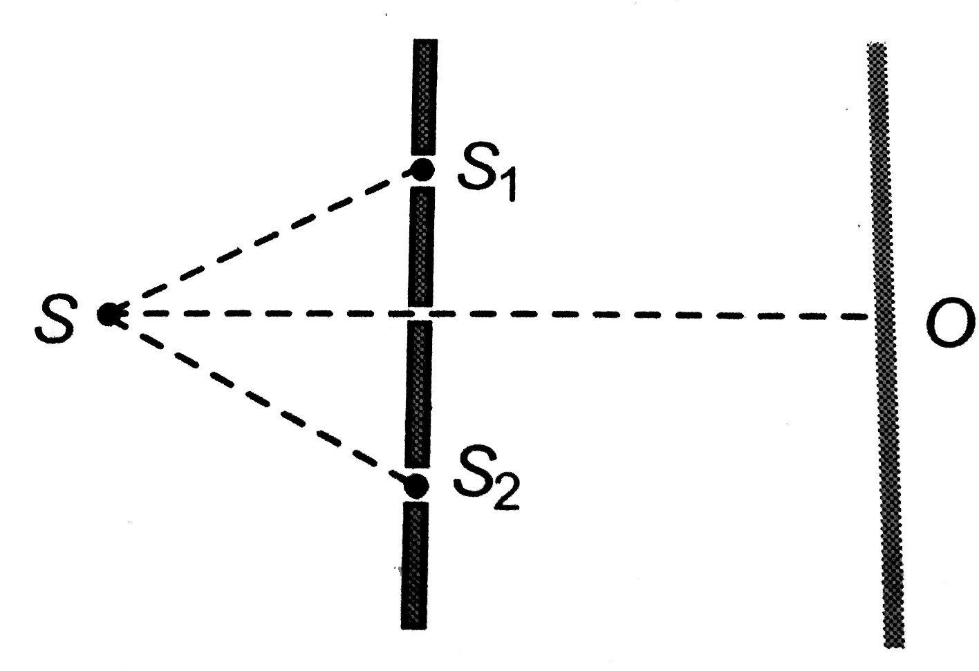
Assertion (A) : In YDSE, as shown in figure, central bright frings is formed at O If a liquid is filled between plane of slits and screen the central bright fringes is shifted in upward direction.
Reasoning (R ) : Path difference at O will increase, so y-coordinate will increase.

A is correct and R is the correct explanation of A
Both A and R are correct but R is not the correct explanation of A
A is correct but R is wrong
Both A and R are wrong
The correct Answer is:D
Step by step video & image solution for Assertion (A) : In YDSE, as shown in figure, central bright frings is formed at O If a liquid is filled between plane of slits and screen the central bright fringes is shifted in upward direction. Reasoning (R ) : Path difference at O will increase, so y-coordinate will increase. by Physics experts to help you in doubts & scoring excellent marks in Class 12 exams.
Similar Questions
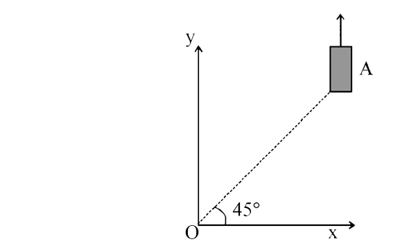
On a frictionless horizontal surface , assumed to be the x−y plane , a small trolley A is moving along a straight line parallel to the y−axis ( see figure) with a constant velocity of (√3−1)m/s . At a particular instant , when the line OA makes an angle of 45(∘) with the x− axis , a ball is thrown along the surface from the origin O. Its velocity makes an angle ϕ with the x− axis and it hits the trolley .
(a) The motion of the ball is observed from the frame of the trolley . Calculate the angle θ made by the velocity vector of the ball with the x−axis in this frame .
(b) Find the speed of the ball with respect to the surface , if ϕ=(4θ)/(3).
 View Solution
Assertion: White light is used in YDSE. Now, a glass slab is inserted in front of the slit S1. Then, red fringe will shift less (in upward direction) compared to violet.
Reason: Refractive index for violet colour will be more.View SolutionWhat is the difference between 2.0m and 2.00m.
View SolutionIn Young.s double slit experiment, what is the path difference between the two light waves forming 5th bright band (fringe) on the screen ?
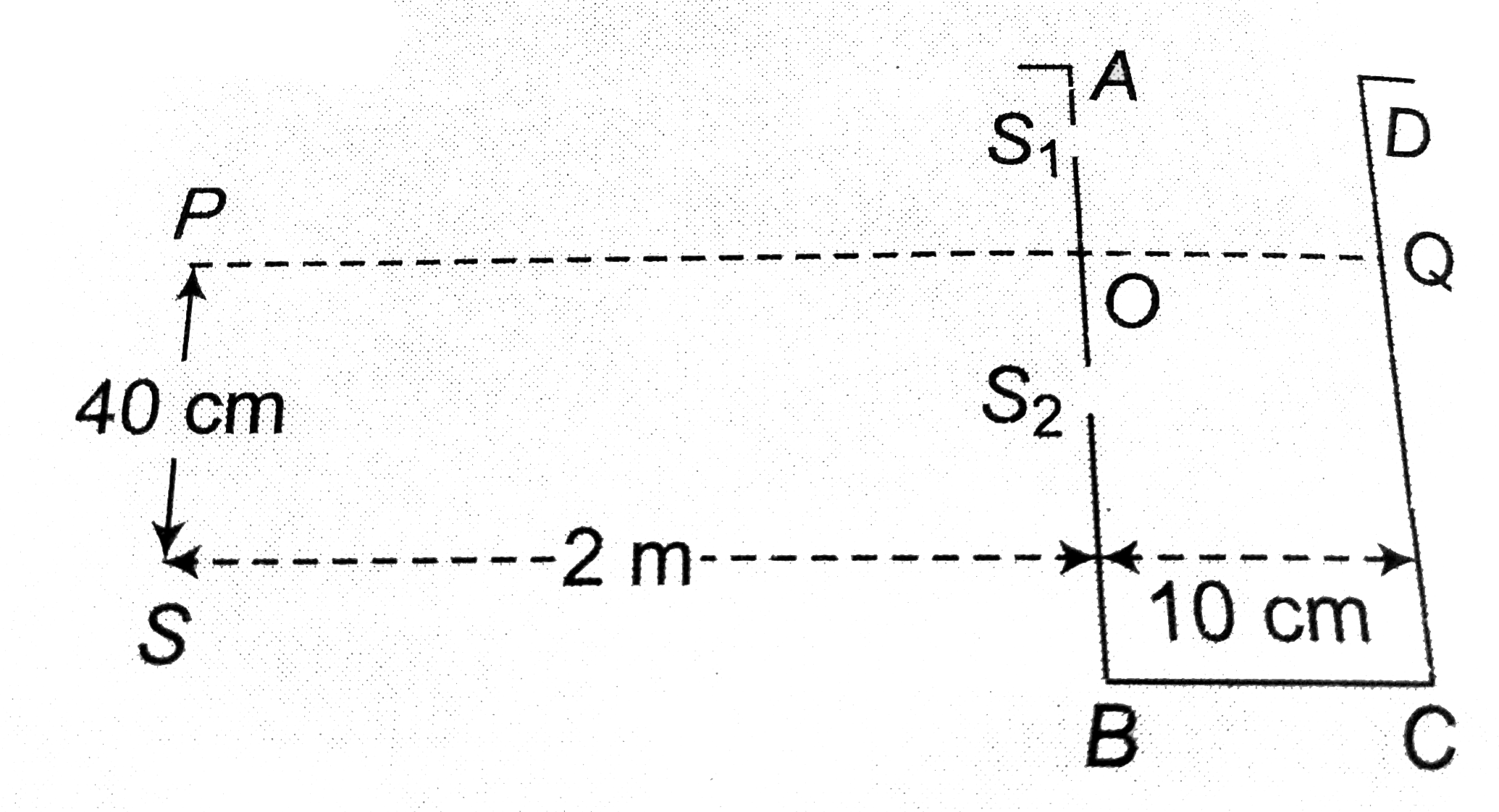
View SolutionA vessel ABCD of 10cm width has two small slits S1 and S2 sealed with idebtical glass plates of equal thickness. The distance between the slits is 0.8mm. POQ is the line perpendicular to the plane AB and passing through O, the middle point of S1 and S2. A monochromatic light source is kept at S,40cm below P and 2m from the vessel, to illuminate the slits as shown in the figure. Calculate the position of the central bright fringe on the other wall CD with respect of the line OQ. Now, a liquid is poured into the vessel and filled up to OQ. The central bright fringe is fiund to be at Q. Calculate the refractive index of the liquid.
 View Solution
In the set up shown in figure, the two slits S1 and S2 are not equidistant from the slit S. The central fringe at O is then
 View Solution
Interference fringes are observed on a screen by illuminating two thin slits 1 mm apart with a light source (λ=632.8nm). The distance between the screen and the slits is 100 cm. If a bright fringes is observed on a screen at a distance of 1.27 mm from the central bright fringe , then the path difference between the waves , which are reaching this point from the slits is close to :
View SolutionAssertion: The pattern and position of fringes always remain same even after the introduction of transparent medium in a path of one of the slit.
Reason: The central fringe is bright or dark is depend upon the initial phase difference between the two coherence sources.View SolutionA : If the phase difference between the light waves emerging from the slits of the Young.s experiment is π-raidan, the central fringe will be dark
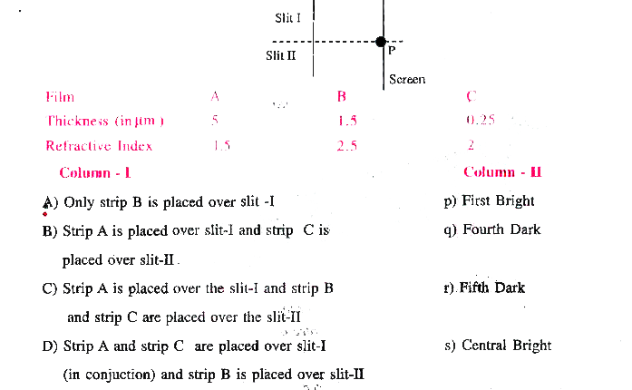
R : Phase difference is equal to (2π/λ) times the path difference.View SolutionA double slit interference pattern is produced on a screen, as shown in the figure, using momochromatic light of wavelength 500 nm. Point P is the location of the central bright fringe, that is produced when light waves arrive in phase without any path difference. A choice of the three strips A, B and C of transparent materials with different thickness and refractive indices is available, as shown in the table. These are placed over one or both of the slits, singularly or in conjunction causing the interference pattern to be shifted across the screen from the original pattern. In the Column - I, how the strips have been placed, is mentioned whereas in the Column-II, order of the fringe at point P on the screen that will be produced due to the placement of the strip(s), is shown. Correctly match both the column.
 View Solution

