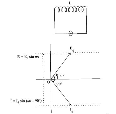
An alternating e.m.f. is applied to a pure inductance. Investigate the phase relationship between current through inductor and em.f. applied to it.
Let a source of alternating e.m.f. be connected to a pure circuit containing a pure inductance L only.
Suppose the alternating em.f. supplied is represented by
E=E0sinωt
If dIdt is the rate of change through L at any instant, then induced e.m.f. in the inductor at the same instant is
e=−LdIdt

To maintain the flow of current in the circuit, applied voltage must be equal and opposte to the induced voltage.
i.e., E=−(−LdIdt)=E0sinωt
dI=E0L=sinωtdt
Integrating both side we get,
I=E0L∫sinωtdt
I=E0L(−cosωtω)
I=−E0ωLcosωt
=−E0ωLsin(π2−ωt) [∵sin(90∘−θ)=cosθ]
I=E0ωLsin(ωt−π2)
The current will be max.
i.e., I=I0 when sin(ωt−π/2) is maximum
∴I0=E0ωL×1=E0ωL
∴I=I0sin(ωt−π2) ........(2)
conclusion : From equation (1) and (2), it is clear that. In a.c. circuit containing L only, I bags behind E by a phase angle of π2.
Here, XL=ωL

Similar Questions
Explain the term 'inductive reactance'.Show graphically the variation of inductive reactance with frequency of the applied alternating voltage.
An a.c. voltage E=E0sinωt is applied across a pure inductor L.Show mathematically that the current flowing through it lags behind the applied voltage by a phase angle of π/2.
View SolutionExplain the term 'inductive reactance'.Show graphically the variation of inductive reactance with frequency of the applied alternating voltage.
An a.c. voltage E=E0sinωt is applied across a pure inductor L.Show mathematically that the current flowing through it lags behind the applied voltage by a phase angle of π/2.
View Solution
Knowledge Check
An alternating e.m.f. is applied to purely capacitive circuit. The phase relation between e.m.f. and current flowing in the circuit is or in a circuit containing capacitance only
Ae.m.f. is ahead of current by π/2BCurrent ahead of e.m.f by π/2CCurrent lags behind e.m.f. by πDCurrent is ahead of e.m.f. by πAn alternating emf, e=300 sin100πt volt, is applied to a pure resistance of 100 Ω. The rms current through the circuit is
A2.12 AB0.212 AC20.12 AD0.0212 AIf an alternating e.m.f. is applied to a series L-R circuit, the phase angle between e.m.f. and current is given by tanθ=ωLR. Hence the power factor of the series L-R circuit is
A1. ωLRB2. RωLC3. RR+ωLD4.R√R2+ω2L2
An alternating e.m.f. 100 cos 100 t volt is connected in series to a resistance of 10 ohm and inductance 100mH. The phase difference between the current in the circuit and the e.m.f. is
View SolutionAn alternating e.m.f. 100 cos 100 t volt is connected in series to a resistance of 10 ohm and inductance 100mH. The phase difference between the current in the circuit and the e.m.f. is
View SolutionThe alternating emf of e=e0 sin ωt is applied across LR series circuit. The impedance and phase angle between current and voltage is
View SolutionAn alternating e.m.f. is applied to a series L-C-R circuit. If the frequency of the applied e.m.f. is more than the resonant frequency of the circuit then the circuit will act as
View SolutionAn alternating e.m.f. of angular frequency ω is applied across an inductance. The instantaneous power developed in the circuit has an angular frequency
View Solution
