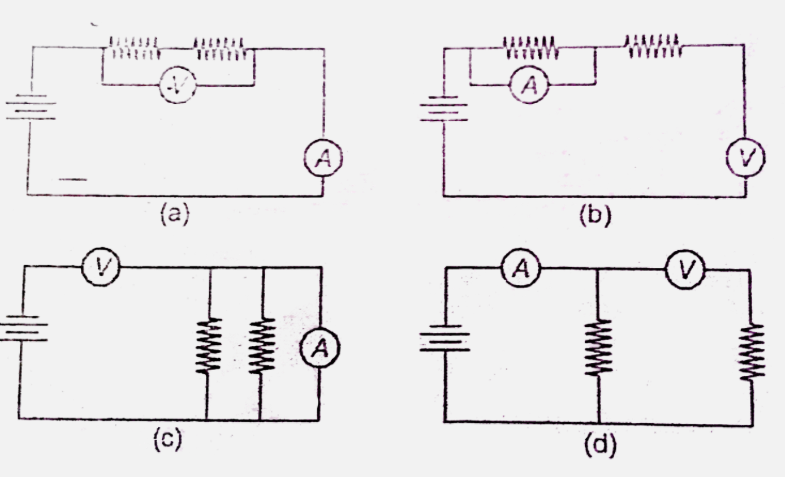
Draw a schematic diagram of a circuit consisting of a battery of 12V, three resistors of , , and connected in parallel, an ammeter to measure the total current through the circuit, voltmeter to measure the potential difference across the combination of resistors.Solution in Punjabi
Step by step video & image solution for Draw a schematic diagram of a circuit consisting of a battery of 12V, three resistors of 5ohm, 10ohm, and 20ohm connected in parallel, an ammeter to measure the total current through the circuit, voltmeter to measure the potential difference across the combination of resistors. by Physics experts to help you in doubts & scoring excellent marks in Class 10 exams.
Updated on:21/07/2023Topper's Solved these Questions
- MAGNETIC EFFECTS OF ELECTRIC CURRENTBOOK - MODERN PUBLICATIONCHAPTER - MAGNETIC EFFECTS OF ELECTRIC CURRENTEXERCISE - EXERCISE
265 Videos
- ELECTRICITYBOOK - MODERN PUBLICATIONCHAPTER - ELECTRICITYEXERCISE - EXERCISE
303 Videos
- REFLECTION AND REFRACTIONBOOK - MODERN PUBLICATIONCHAPTER - REFLECTION AND REFRACTIONEXERCISE - EXAMPLE
138 Videos
Similar Questions
Write the S.I. unit of magnetic field →B.
View SolutionDefine electric current and give its unit
View SolutionA concave mirror of focal length 20 cm forms a real image at a distance of 40 cm. find the position of the object.
View SolutionDraw a circuit diagram of an electric circuit containing a cell, a key, an ammeter, a resistance of 2Ω in series with a combination of two resistors (4Ω each) in parallel and a voltmeter across the parallel combination. Will the potential difference across the 2Ω resistor be the same as that across the parallel combination of 4Ω resistors ? Give reason.
View SolutionDraw a circuit diagram for a circuit in which two resistors A and B are connected in series with a battery and voltmeter is connected to measure the potential difference across the resistor A.
View SolutionRedraw the circuit of question 1, putting in an ammeter to measure the current through the resistors and a voltmeter to measure potential difference across the 12 Ω resistor. What would be the readings in the ammeter and the voltmeter?
View SolutionWhich circuit diagram shows voltmeter V and ammeter A correctly positioned to measure the total potential difference of the circuit and the current through each resistor?
View SolutionRedraw the circuit of Question 1, putting in an ammeter to measure to current through the resistors and a voltmeter to measure the potential difference across the 12Ω resistor. What would be the readings in the ammeter and the voltmeter?
View SolutionDraw a schematic circuit diagram for a circuit in which three resistors R1,R2 and R3 a plug key under dosed condition, an ammeter are joined In series with a 5V battery. Also a voltmeter is connected to measure the potential difference across the resistor R1
View SolutionDraw a circuit diagram of an electric circuit containing a cell, a key, an ammeter, a resistor of 2Omega in series with a combination of two resistors [ 4Omega each] in parallel and a voltmeter across the parallel combination. Will the potential difference across the 2Omega resistor be the same as that across the parallel combination of 4Omega resistors? Give reason.
View SolutionWhich circuit diagram shows voltmeter V and ammeter A correctly positioned to measure the total potential difference of the circuit and the current through each resistor?
View SolutionDraw a circuit diagram of an electric circuit containing a cell, a key, an ammeter, a resistance of 2Ω in series with a combination of two resistors (4Ω each) in parallel and a voltmeter across the parallel combination. Will the potential difference across the 2Ω resistor be the same as that across the parallel combination of 4Ω resistors ? Give reason.
View SolutionRedraw the circuit of 9.39, putting in an ammeter to measure the current through the resistors and a voltmeter to measure the potential difference across the 12Omega resistor. What would be the readings in the ammeter and the voltmeter ?
View SolutionVoltmeter V and Ammeter A are used to measure the total potential difference of the circuit and the current through each resistor. Which is the correct circuit ?

View SolutionRedraw the circuit, putting in an ammeter to measure the current through the resistors and a voltmeter to measure the potential difference across the 12Ω resistor. What would be the readings in the ammeter and the voltmeter?
View SolutionDraw a circuit diagram of an electric circuit containing a cell, a key, an ammeter, a resistor of 2Omega in series with a combination of two resistors ( 4Omega each) in parallel and a voltmeter across the parallel combination. Will the potential difference across the 2 Omega resistor be the same as that across the parallel combination of 4Omega resistors? Give reason.
View Solution
