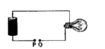
Brad sets up an electrical circuit as shown in the figure. He connects points P and Q of the circuit with four different rods made of four different materials - glass, wood, copper, and asbestos.

The bulb in the circuit will not light up when points P and Q are connected with
Glass rod
Wood rod
Copper rod
Asbestos rod
Step by step video & image solution for Brad sets up an electrical circuit as shown in the figure. He connects points P and Q of the circuit with four different rods made of four different materials - glass, wood, copper, and asbestos. The bulb in the circuit will not light up when points P and Q are connected with by Physics experts to help you in doubts & scoring excellent marks in Class 6 exams.
Topper's Solved these Questions
Similar Questions
Brad sets up an electrical circuit as shown in the given figure. He connects points P and Q of the circuit with four different rods made of four different materials - glass, wood, copper, and asbestos.

The bulb in the circuit will not light up when points P and Q are connected withView SolutionTommy sets up an electrical circuit as shown in the figure. He connects points P and Q with different materials.
The bulb will light up when points P and Q are connected by a plate made ofView Solution
Knowledge Check
- Question 1 - Select One
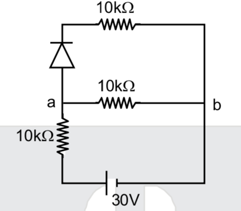
There is a electric circuit as shown in the figure. Find potential difference between points a and b.
 A3VB15VC10VD5V
 - Question 2 - Select One
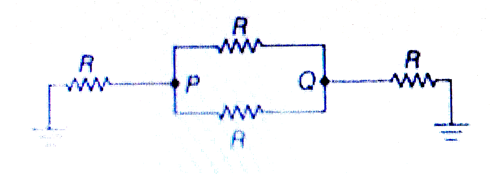
The net resistance between points P and Q in the circuit shown in figure is
 AR/2B2R/5C3R/5DR/3
 - Question 3 - Select One
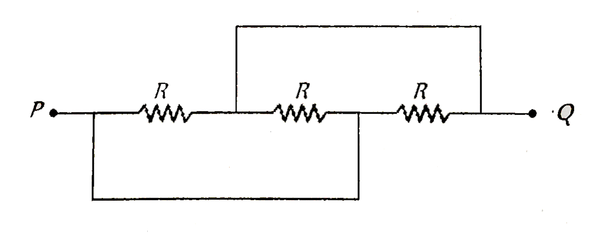
The equivalent resistance between the points P and Q of the circuit given is
 AR4BR3C4RD2R
Tommy sets up an electrical circuit as shown in the figure. He connects points P and Q with different materials.

The bulb will light up when points P and Q are connected by a plate made ofView SolutionThe effective resistance between points P and Q of the electrical circuit shown in the figure is
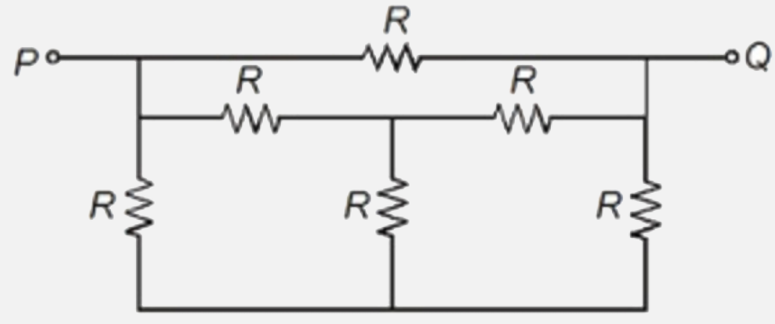 View Solution
The effective resistance between points P and Q of the electrical circuit shown in the figure is :
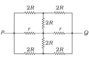 View Solution
The effective resistance between points P and Q of the electrical circuit shown in the figure is
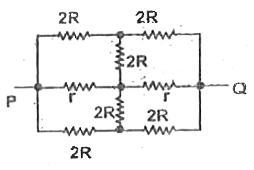 View Solution
The potential difference between points a and b of circuits shown in figure is
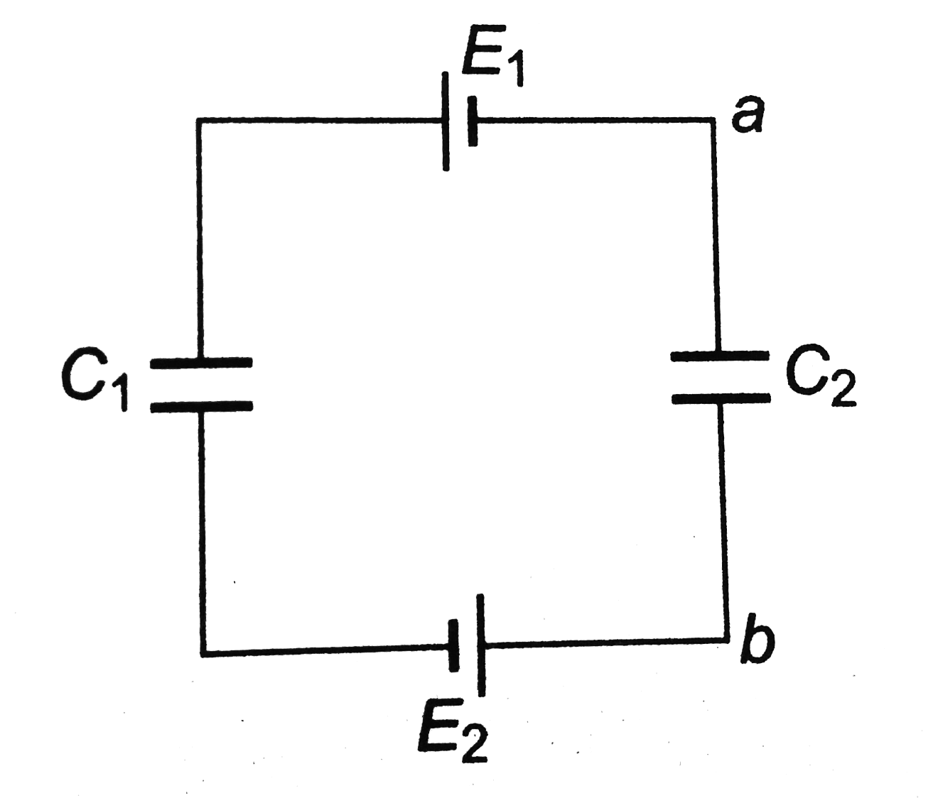 View Solution

