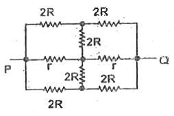
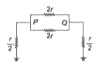
The effective resistance between points P and Q of the electrical circuit shown in the figure is
A
2RrR+r
B
8(R+r)3R+r
C
2r+4R
D
5R2+2r
Video Solution
Text Solution
The correct Answer is:A
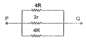
The circuit can be reduced to the one given alongside
Re=2rRr+RHence, (A) is correct
|
Updated on:21/07/2023
Topper's Solved these Questions
- BOOK - FIITJEECHAPTER - CURRENT ELECTRICITYEXERCISE - Exercise9videos
CURRENT ELECTRICITY
- BOOK - FIITJEECHAPTER - CURRENT ELECTRICITYEXERCISE - Comprehension Based Type-13videos
CURRENT ELECTRICITY
- BOOK - FIITJEECHAPTER - CURRENT ELECTRICITYEXERCISE - SOLVED PROBLEMS (SUBJECTIVE)10videos
CURRENT ELECTRICITY
- BOOK - FIITJEECHAPTER - COLLISION EXERCISE - (NUMERICAL BASED QUESTIONS)4videos
COLLISION
- BOOK - FIITJEECHAPTER - ELASTICITY AND WAVES EXERCISE - Assignment Problems (Objective) Level-II15videos
ELASTICITY AND WAVES
Similar Questions
Knowledge Check
- Question 1 - Select One
What is the effective resistance between points P and Q?
 Ar2Br3C2R3D4r3
 - Question 2 - Select One
What is the effective resistance between points P and Q?
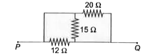 A5ΩB10ΩC15ΩD20Ω
 - Question 3 - Select One
The equivalent resistance between point x and y, of the circuit as shown in the figure is
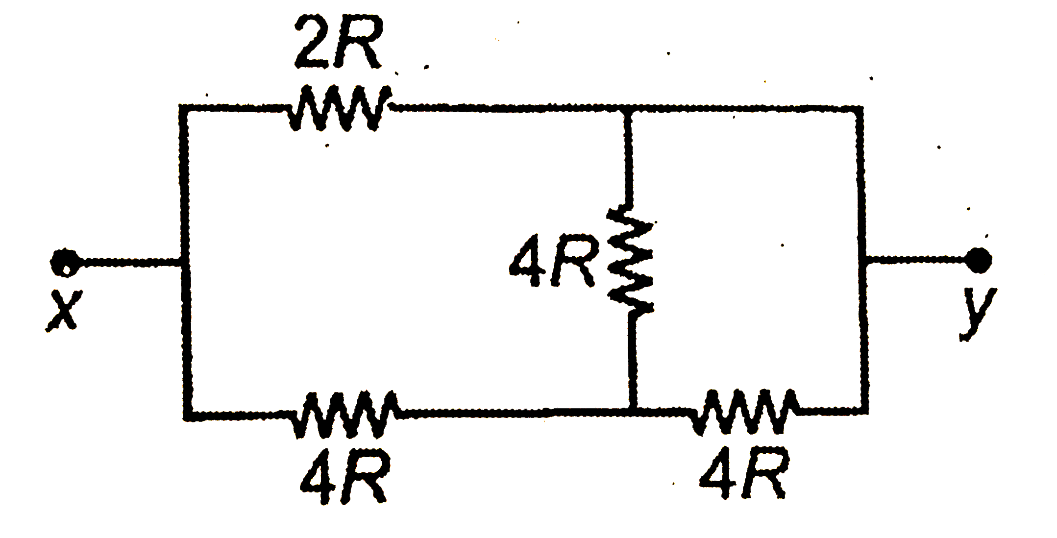 ARB3R2C3R4D8R5
Potential difference between the points P and Q in the electric circuit shown is
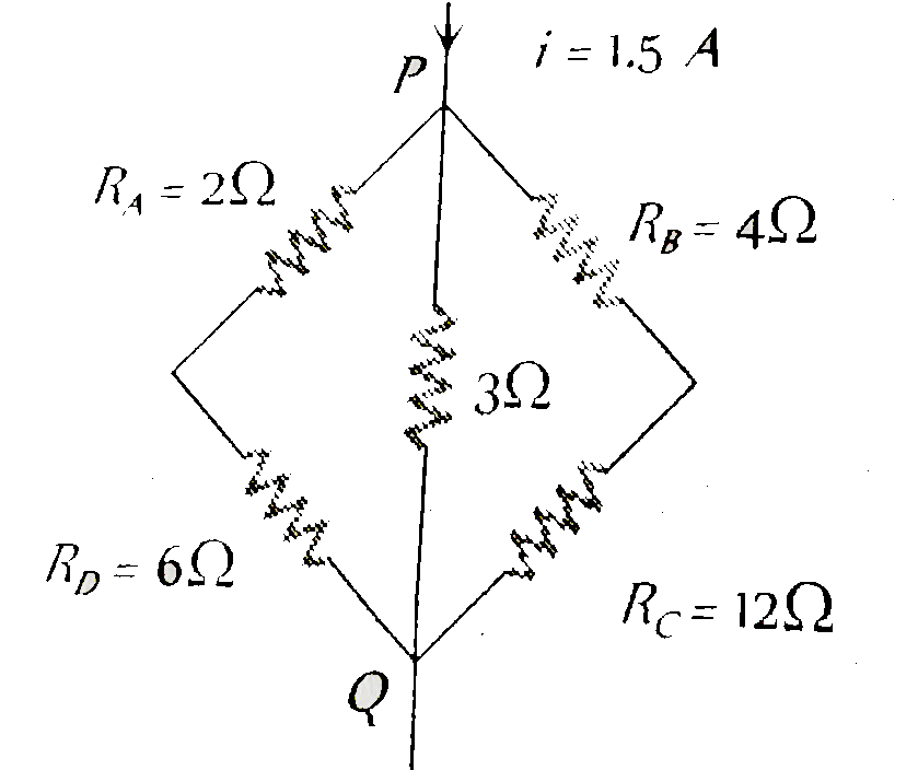 View Solution
The effective resistance between the points A and B in the figure is
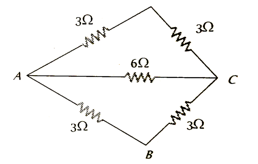 View Solution
The effective resistance between P and Q in the given circuit is
 View Solution
The equivalent resistance between the points P and Q of the circuit given is
 View Solution
The net resistance between points P and Q in the circuit shown in figure is
 View Solution


