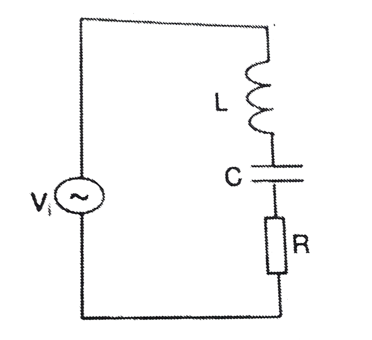
An alternating voltage of frequency f is applied across LCR circuit. Let be the resonance frequency for the circuit. Will the current in the circuit lag, lead or remain in phase with the applied voltage when
? Explain your answer in each case.Solution in Punjabi
Step by step video & image solution for An alternating voltage of frequency f is applied across LCR circuit. Let f_r be the resonance frequency for the circuit. Will the current in the circuit lag, lead or remain in phase with the applied voltage whenf>f_r? Explain your answer in each case. by Physics experts to help you in doubts & scoring excellent marks in Class 12 exams.
Topper's Solved these Questions
Similar Questions
A lamp is connected in series with a capacitor to a high frequency a.c. source. How will the glow of the lamp change, when it is connected directly to the same source? Explain your answer.
02:57View SolutionAssuming the earth to be a sphericl conductor of radius 6400 km, calculate its caacitance. Given 14πε0=9×10⁹Nm2^−2
06:01View SolutionIn a series LCR circuit, the frequency of the source is more than resonance frequency. The current in the circuit leads the voltage in phases(True/false).
02:47View SolutionSTATEMENT-1: In a series LCR circuit at resonance, the voltage across the capacitor or inductor may be more than the applied voltage.
STATEMENT-2: At resonance in a series LCR circuit, the voltages across inductor and capacitor are out of phase.05:03View SolutionAn LCR circuit is connected to a source of alternating current. At resonance, the applied voltage and the current flowing through the circuit will have a phase difference of
01:37View SolutionIn LCR circuit at resonance current in the circuit is 10√2A. If tnow frequency of the source is changed such that now current lags by 45∘ that applied voltage in the circuit . Which of the following is correct.
02:40View SolutionAn alternating voltage of frequency f is applied across a series LCR circuit.Le f_(r) be the resonance frequency for the circuit.Will the current in the circuit lag, lead or remain in phase with the applied voltage when (i) f gt f_(r) ,(ii) f lt f_(r) ? Explain your answer in each case.
01:04View SolutionIn the following circuit the current is in phase with the applied voltage. Therefore, the current in the circuit and the frequency of the source voltage respectively, are
 05:52View Solution
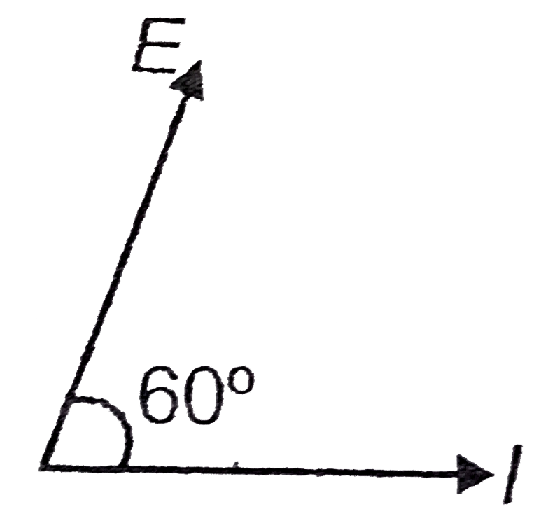
Phase relationship between current (l) and applied voltage (E) for a series LCR circuit is shown here. ω0 = Resonant angular frequency of the circuit and ω= Applied angular frequency .
 01:37View Solution
f आवृत्ति की प्रत्यावर्ती वोल्टता एक श्रेणी LCR परिपथ पर आरोपित की गई है। माना frपरिपथ की अनुनादी आवृत्ति है। परिपथ में बहने वाली धारा आरोपित वोल्टता से पश्चगामी, अग्रगामी या समान कला में है जब-
(i) f>fr (ii) f<fr
प्रत्येक स्थिति में अपने उत्तर की व्याख्या कीजिए।View SolutionAn alternating voltage of frequency f is applied across a series LCR circuit. Let f_r be the resonance frequency for the circuit. Will the current in the circuit lag, lead or remain in phase with the applied voltage when (i) f gt f_r (ii) fltf_r (iii) f=f_r ? Explain your answer in each case.
03:39View SolutionAn a.c source of original frequency omega is applied to a series resonant, L,C,R circuit. If the resonant frequency is omega_0 then the current in the circuit will lag behind the voltage if:
01:40View Solutionआवृत्ति f की एक प्रत्यावर्ती वोल्टता एक श्रेणीक्रम LCR परिपथ के सिरों पर जोड़ी जाती है। मानाकि परिपथ के लिये अनुनाद आवृत्ति fr है। परिपथ में धारा आरोपित वोल्टता से पीछे रहेगी या आगे रहेगी या कला में रहेगी जब (1) f>fr , (ii) f<fr ? प्रत्येक स्थिति में अपना उत्तर स्पष्ट कीजिये।
02:20View SolutionAn LCR circuit is connected to a source of alternating current. At resonance, the applied voltage and the current flowing through the circuit will have a phase difference of
02:38View SolutionIn a series LCR circuit, the frequency of the source is more than resonance frequency. The current in the circuit leads the voltage in phases(True/false).
01:55View SolutionPhase relationship between current (l) and applied voltage (E) for a series LCR circuit is shown here. ω0 = Resonant angular frequency of the circuit and ω= Applied angular frequency .
 02:41View Solution

