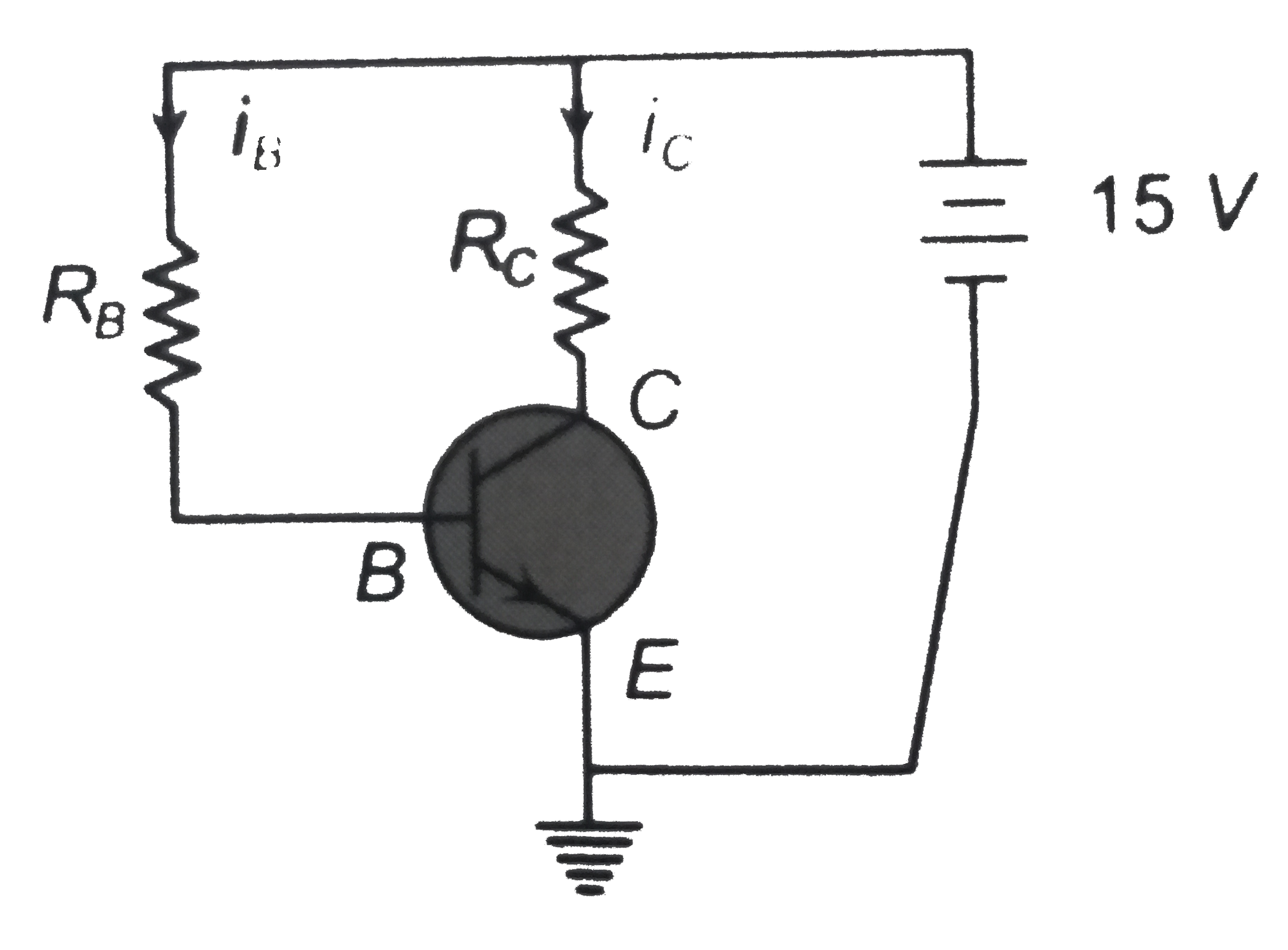
In a common emitter n−p−n transistor, VBE=0.7V, Vcc=12VRL=1kohm. The minimum value of Ic (in mA) to drive the transistor in saturation is
'(## CEN_SRK_PHY_JEE_C31_E01_035_Q01##)'
To find the minimum value of collector current IC required to drive the NPN transistor into saturation, we can follow these steps:
Step 1: Understand the Circuit
In a common emitter configuration, the transistor is driven into saturation when the collector current IC is maximized. The voltage across the load resistor RL will be VCC−VCE(sat), where VCE(sat) is typically around 0.2V for silicon transistors.
Step 2: Calculate the Voltage Across the Load Resistor
Given:
- VCC=12V
- VBE=0.7V (this is the base-emitter voltage)
- VCE(sat)≈0.2V
The voltage across the load resistor RL when the transistor is in saturation can be calculated as:
VRL=VCC−VCE(sat)=12V−0.2V=11.8V
Step 3: Calculate the Collector Current IC
Using Ohm's law, the collector current IC can be calculated as:
IC=VRLRL
Substituting the values:
- RL=1kΩ=1000Ω
IC=11.8V1000Ω=0.0118A=11.8mA
Step 4: Conclusion
The minimum value of IC to drive the transistor into saturation is:
11.8mA
---
In a common emitter configuration, the transistor is driven into saturation when the collector current IC is maximized. The voltage across the load resistor RL will be VCC−VCE(sat), where VCE(sat) is typically around 0.2V for silicon transistors.
Given:
- VCC=12V
- VBE=0.7V (this is the base-emitter voltage)
- VCE(sat)≈0.2V
VRL=VCC−VCE(sat)=12V−0.2V=11.8V
Using Ohm's law, the collector current IC can be calculated as:
IC=VRLRL
Substituting the values:
- RL=1kΩ=1000Ω
IC=11.8V1000Ω=0.0118A=11.8mA
The minimum value of IC to drive the transistor into saturation is:
11.8mA
Topper's Solved these Questions
Similar Questions
Maximum power loss (in watt) in the given circuit is
'(##CEN_KSR_PHY_JEE_C24_E01_020_Q10##)'
View SolutionIn the circuit shown, the batteries have emf E(t)=E2=1 (V),E3=2.5V and the resistance R1=10ohm,R2=20ohmCapacitance C=10μF. The magnitude of charge (in μC ) on the left plate of the capacitor C at steady state is
'(##CEN_KSR_PHY_JEE_CO20_E01_022_Q17##)'
View Solution
Knowledge Check
In common - emitter configuration of a transistor, the base current IE=2μA,α=0.9 then the value of IC is
A3.0μAB2.25μAC4.9μAD1.8μAIn a common base configuration (transistor circuit) IE=1mA,IC=0.95mA. The value of base current is
A195 mAB0.05 mAC105 mAD0.95 mAIn the following common emitter circuit if β=100,VCE=7V,VBE=Negligible, RC=2kΩ then IB=?
 A0.01mAB0.04mAC0.02mAD0.03mA
In the given circuit, the voltmeter records 5V. The resistance (in ohm ) of the voltmeter is :
'(##CEN_KSR_PHY_JEE_CO20_E01_031_Q25##)'
View SolutionIn the circuit điagram shown, Xc=100ohmXt=200Ω and R=100ohm. The effective current throagh the source is m√n ampere. Find (m+n).
'(##CEN_KSR_PHY_JEE_C24_E01_022_Q12##)'
View SolutionIf the current in the circuit sbown below, varying as a function of time is i0sin500t, then find io.
'(##CEN_KSR_PHY_JEE_C24_E01_038_Q21##)'
View SolutionFind the potential difference |leftVs−VAright| (in volt) between the plates of the capacitor C shown in the figure, if the sources have emfs E,=4V and E2=1V and the resistances are equal to R1=10ohm,R2=20ohm and R3=30ohm. The internal resistances of the sources are neglectable

View SolutionIn a circuit shown, voltmeter reads 3V and the ammeter reads 2A. The emf E (in volt) is
'(##CEN_KSR_PHY_JEE_CO20_E01_021_Q16##)'
View Solution
